Rockwell Automation 2100 CENTERLINE Motor Control Center (MCC) Units with Horizontal Operating Handl User Manual
Page 8
8
Rockwell Automation Publication 2100-IN060D-EN-P - March 2014
CENTERLINE 2100 Motor Control Center (MCC) Units with Horizontal Operating Handles
3. Install other cables or devices.
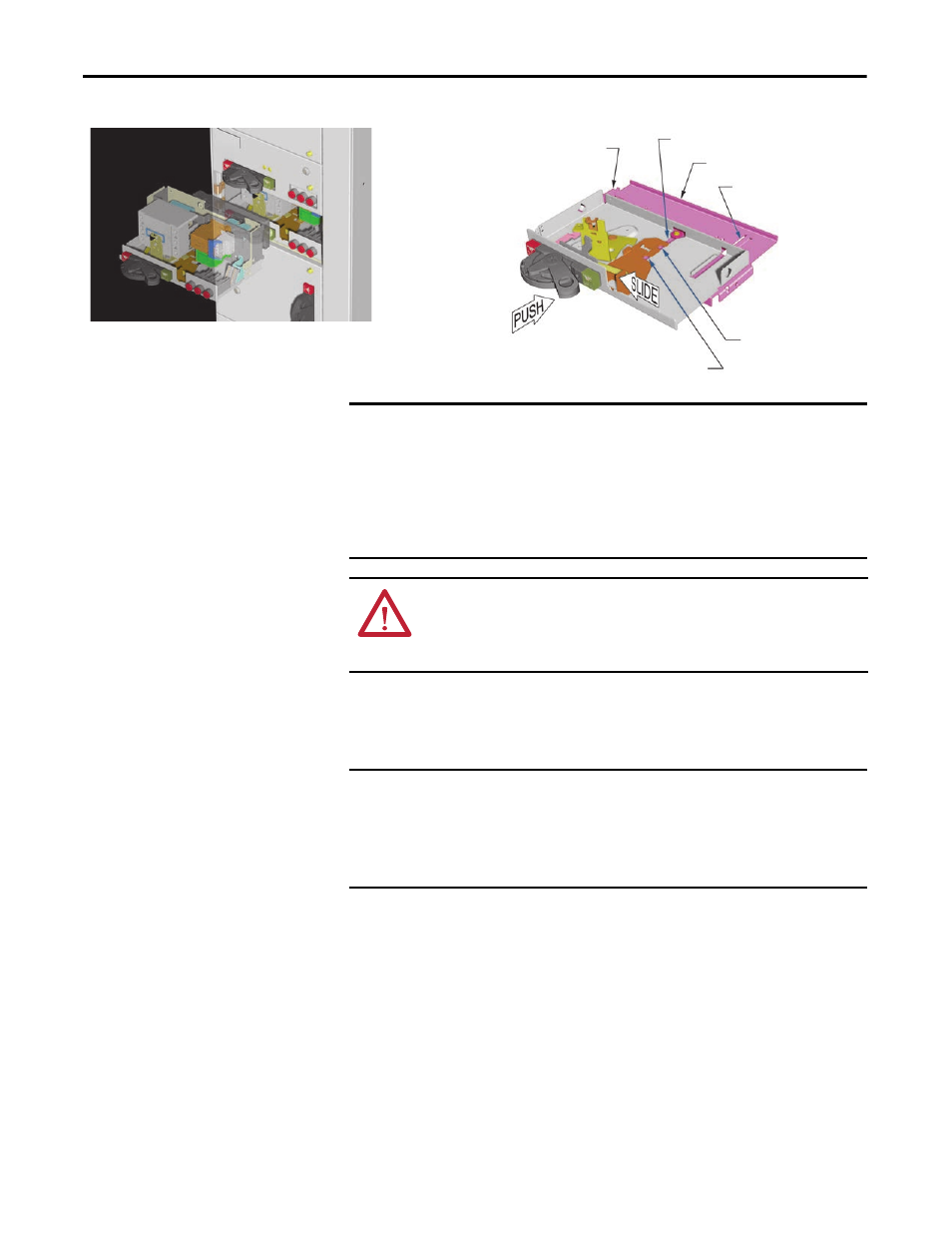
Bushing Slot
Unit Support Pan
Right Unit Guide
Left Unit Guide
Disconnected Position
Normal Operating Position
Unit devices have been
omitted for clarity.
IMPORTANT
Note that there are two positions available (normal operating and
disconnected). In the normal operating position, the power and ground stabs
are connected to their respective busses. In the disconnected position, the unit
is partially removed from the MCC and the intermediate slot in the interlock
plate is in line with the bushing located in the unit support pan. When the unit
is locked in this position, the unit power and ground stabs are disengaged. This
position can be used to prevent insertion of a unit into the MCC.
ATTENTION: For proper operation of the latch/interlock mechanism, a style 3
unit-support pan with bushing must be used below the unit. If the unit support
pan with bushing is not used, the unit could be removed under load, resulting in
injury or death.
TIP
For the CENTERLINE 2100 MCC units with swing-out door latches, it is
necessary to rotate the movable portion of the latch bracket to a vertical
orientation to avoid interference when installing the unit.
IMPORTANT
Be sure to comply with the National Electric Code 6.7 ft (2 m) unit handle-to-
floor height limitation, as identified in NEC 2005 Article 404.8(A) and UL
standard 845, for units in the topmost location of a vertical section.
A unit operating handle extender kit, catalog number 2100H-NE1, is available
for any handles higher than 6.7 ft (2 m) off of the ground.