Rockwell Automation 7703E Medium Voltage SMC OEM Components - 10-15 kV User Manual
Page 43
Rockwell Automation Publication 7703E-IN001E-EN-P - July 2014
43
Final Test Procedures
Chapter 7
6. With the gate pulses on, check the voltage again on each gate-driver board
as described in
above. The voltage should be 4…5V DC.
7. Locate the Portable Test Power Supply that was included with the
equipment, and verify that the rating corresponds to the available power
system (i.e., 110/120V AC or 220/240V AC). Plug the unit into the
power source, and plug the green connector into J1 on each of the gate
driver boards (see
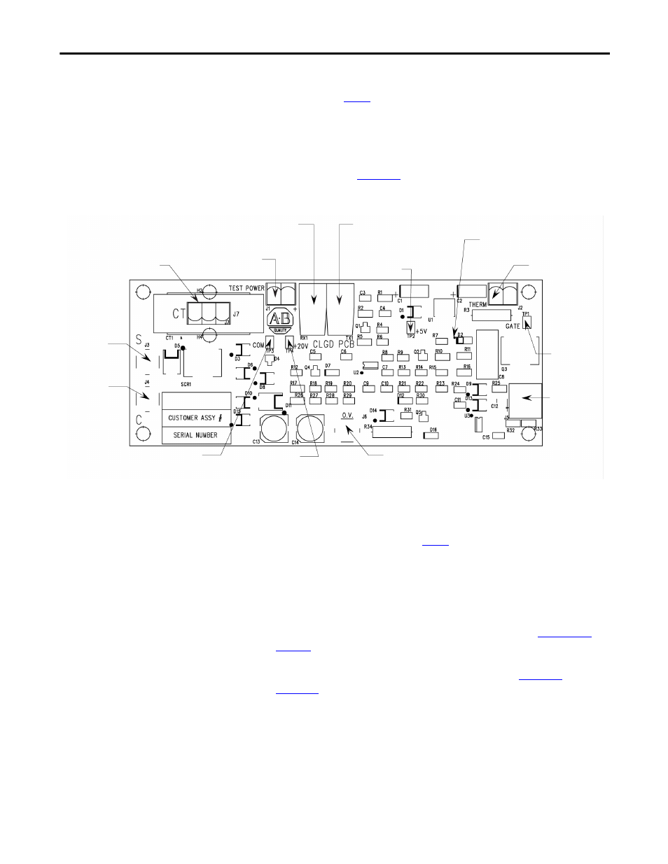
Figure 21 - Test Power Application on Gate Driver Board
8. The yellow LED on the upper right-hand side of the energized gate driver
circuit should be lit (it may appear dim, depending on ambient light
conditions). While the gate pulses are still on, check the voltage on each
gate driver board as described in
above. The voltage should be
10…12V DC. If the voltage is less than 5V, then you have a bad gate drive
board. Do not leave the Portable Test Power Supply connected to a bad
gate driver board. The power supply adapter will burn up if the gate driver
board is shorted.
9. A more detailed check is performed by verifying the actual gate pulses by
connecting an oscilloscope between TP1 and TP3 (-) (see
). To check gate pulses, the pulse generator must be enabled
(i.e. SW2 toggled up) and the Portable Test Power Supply should be
connected to J1. The pulse should appear as shown in
.
Temperature signal
fiber optic transmitter
Yellow LED
Thermistor
connector
Gate signal
test point
Gate/cathode
connector
Overvoltage
+20V test point
+5V test point
Gate signal
fiber optic receiver
Plug-in test power
supply
Current loop
CT connector
Snubber
terminal
Cathode
terminal
Common
test point