Rockwell Automation 7703E Medium Voltage SMC OEM Components - 10-15 kV User Manual
Page 24
24
Rockwell Automation Publication 7703E-IN001E-EN-P - July 2014
Chapter 3
PowerBrick™ Installation
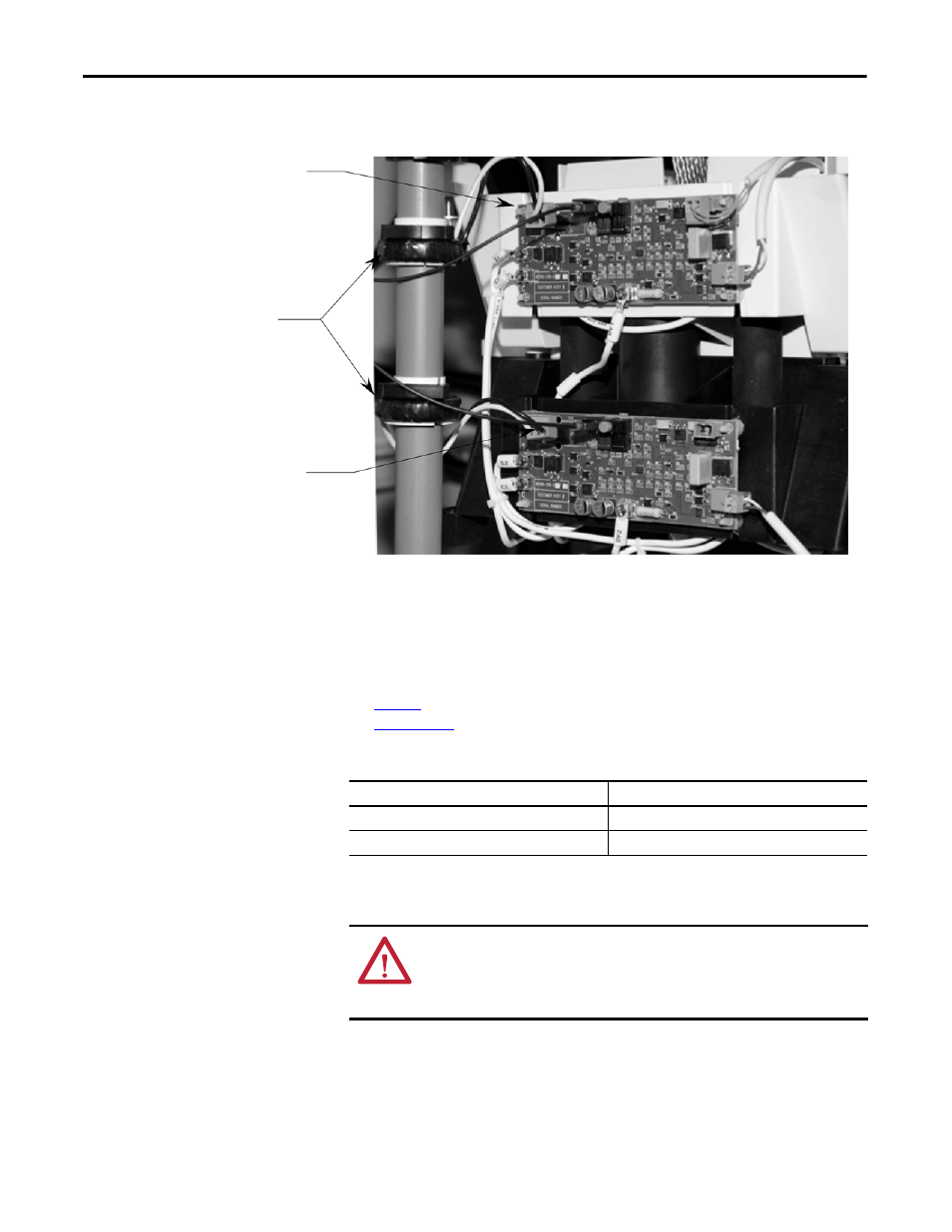
Figure 10 - Connection of CLGD CTs to Gate Driver Board
The CT assembly has a loop cable which passes through the tube and connects to
terminal blocks above and/or below the assembly (depending on how the
assembly is implemented). The three phases of loop cables are connected in series
and to the secondary of the power supply transformer. The transformer rating
and secondary voltage are selected to provide 40 or 50 amps in the loop cable.
See
for matching the loop length to the power supply transformer rating.
See
for part numbers.
Table 5 - Matching Loop Length to Power Supply Transformer Rating
CLGD CT
Connection
Terminal
CLGD CTs
CLGD CT
Connection
Terminal
Power Supply Transformer Rating
Total Loop Length for #6 AWG Cable
50 VA, 115/230:0.6V
21 feet ± 4 in. (6.4 m ± 10 cm)
100 VA, 115/230:1.5V
50 feet ± 8 in. (15.2 m ± 20 cm)
(1)
(1) The 50-foot length is 3 x 14 ft HV wire plus 8 ft LV wire.
ATTENTION: The loop cable length must be as specified above. The loop cable is
the load for the transformer and establishes the loop current. If it is not correct,
a longer length will not provide sufficient power to the gate driver boards, and a
shorter length will overload the cable or transformer.