Dielectric test – Rockwell Automation 7703E Medium Voltage SMC OEM Components - 10-15 kV User Manual
Page 40
40
Rockwell Automation Publication 7703E-IN001E-EN-P - July 2014
Chapter 7
Final Test Procedures
• The bypass vacuum contactor or breaker (and capacitor contactor if
applicable) must have a fast drop-out time (typically 100 milliseconds or
less).
Dielectric Test
1. Remove the ribbon cable and ground wires from the voltage sensing board,
and isolate the ends to prepare for the Hi-Pot test.
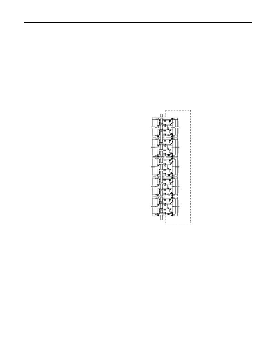
2. Jumper the line and load terminals together within each phase as shown in
.
Figure 19 - Example of Jumper Positioning for Hi-pot Test
3. Measure the resistance between the line and load sides of each PowerBrick
phase assembly to make sure there is zero resistance. This indicates that the
jumpers are properly set.
4. Perform a Hi-Pot test as required by the applicable local codes and
standards. Typical levels for field testing are two times the rated voltage of
the equipment.
5. After the Hi-Pot remove the heatsink jumpers. Re-connect the feedback
board wires.
6. Perform a resistance check for each SCR. The SCR resistance can be
checked directly at the device or at the leads on the gate driver board.
a. The gate-to-cathode resistance should range from 10…40 ohms for all
styles.
b. The cathode-to-cathode resistance can also be checked and should be
between 20…32 ks per brick.
Jumper