Determining mounting order – Rockwell Automation 2094-SEPM-B24-S Kinetix 6000M IDM Power Interface Module User Manual
Page 5
Kinetix 6000M Integrated Drive-Motor Power Interface Module 5
Publication 2094-IN016A-EN-P - February 2012
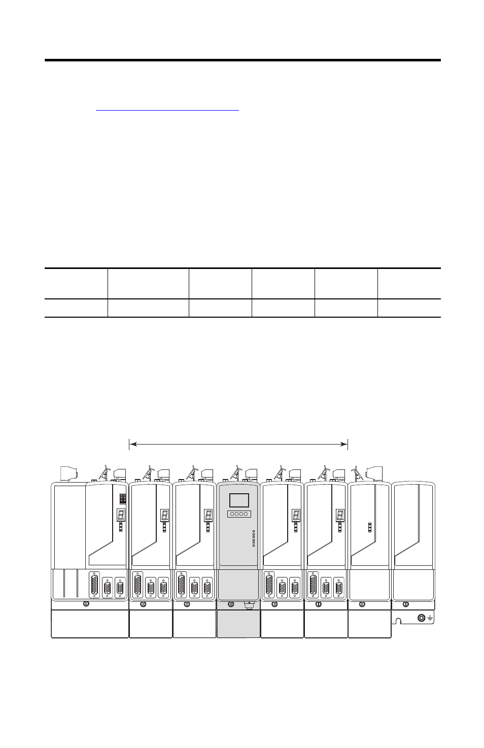
Determining Mounting Order
diagram below and mount the modules in the
order (left to right) shown. Install modules according to power utilization (highest to lowest)
from left to right starting with the highest power utilization. If power utilization is unknown,
position modules (highest to lowest) from left to right based on the IPIM or AM module
continuous power rating (kW).
Power utilization is the average power (kW) consumed by a servo axis. If the servo axis has been
sized by using Motion Analyzer software, version 6.000 or later, the calculated axis power
required can be used for power utilization. If the servo axis has not been sized in Motion
Analyzer, the following table showing the maximum continuous power for IPIM and AM
modules can be used to determine desired location on a power rail.
Module Type and Continuous Power Output
The IPIM module may be installed on a power rail with an IAM module configured as a
common bus follower, but you will be responsible for configuring the leader for the appropriate
additional capacitance in the follower power rail, including the IPIM module.
Module Mounting Order Example
2094-BM05-S
Axis Module
2094-SEPM-B24-S
IPIM Module
2094-BM03-S
Axis Module
2094-BM02-S
Axis Module
2094-BM01-S
Axis Module
2094-BMP5-S
Axis Module
22.0 kW
15.0 kW
13.5 kW
6.6 kW
3.9 kW
1.8 kW
Highest Power Utilization
Lowest Power Utilization
Integrated Axis
Module
Axis Modules
Shunt
Module
Slot Filler
Module
IPIM Module
Axis Modules