Safe-off connector, Enable input – Rockwell Automation 2094-SEPM-B24-S Kinetix 6000M IDM Power Interface Module User Manual
Page 11
Kinetix 6000M Integrated Drive-Motor Power Interface Module 11
Publication 2094-IN016A-EN-P - February 2012
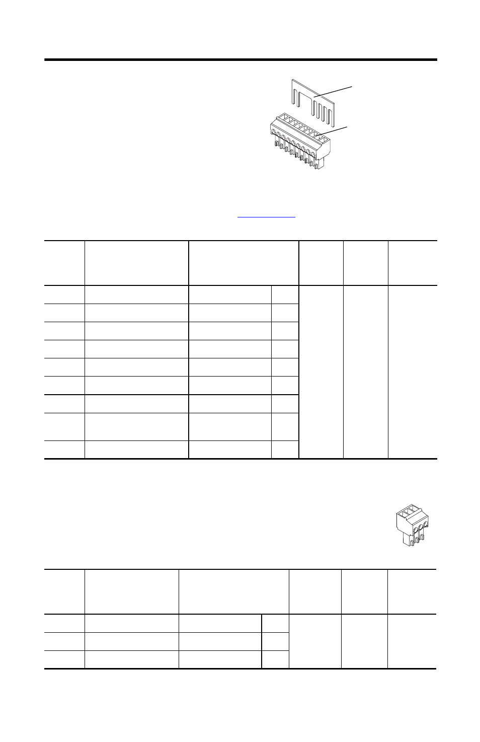
Safe-off Connector
Each IPIM module ships with the wiring-plug
header and motion-allowed jumper installed in the
Safe-off Connector. With the jumper installed, the
safe-off feature is not used.
This connector extends the safe-off signals for use in
wiring single and multiple safe-off drive
configurations, or to jumper around (not use) the safe-off feature. Refer to the Integrated
Drive-Motor System User Manual, publication
2094-UM003
, for further information.
Enable Input
One digital input is supplied to enable all connected IDM units. The enable
status is transmitted to all of the IDM units through the CAN bus.
Terminal
Description
Signal
Strip
Length
mm (in.)
Torque
N•m (lb•in)
Min/Max
Wire Size
(1)
mm
2
(AWG)
(1)
Maximum/minimum that the connector will accept—these are not recommendations.
1
Feedback Monitoring 2+
FDBK2+
F2+
7.0 (0.275)
0.235 (2.0)
0.14…1.5
(30…14)
2
Feedback Monitoring 2-
FDBK2-
F2-
3
Feedback Monitoring 1+
FDBK1+
F1+
4
Feedback Monitoring 1-
FDBK1-
F1-
5
Safety Enable Input 2
SAFETY ENABLE2+
SE2
6
Safety Enable Common
SAFETY ENABLE-
SE-
7
Safety Enable Input 1
SAFETY ENABLE1+
SE1
8
Safety Bypass Supply, +24V DC,
320 mA max
24+
24+
9
Safety Bypass supply, Common
24V COM
24-
Terminal
Description
Signal
Strip Length
mm (in.)
Torque
N•m (lb•in)
Min/Max
Wire Size
(1)
mm
2
(AWG)
(1)
Maximum/minimum that the connector will accept—these are not recommendations.
1
+24V DC Enable Supply
ENABLE 24V+
+
7.0 (0.275)
0.235 (2.0)
0.14…1.5
(30…14)
2
Enable Input
ENABLE INPUT
EN
3
24V DC Common
ENABLE 24V COM
-
1
F2+
F2-
F1+
F1-
SE2
SE-
SE1
24+
24-
Motion-allowed Jumper
(not installed)
Wiring Plug Header
1
+
EN
-