Wiring the connectors, Hybrid cable dc bus connector, Hybrid cable communication signals connector – Rockwell Automation 2094-SEPM-B24-S Kinetix 6000M IDM Power Interface Module User Manual
Page 10
10 Kinetix 6000M Integrated Drive-Motor Power Interface Module
Publication 2094-IN016A-EN-P - February 2012
Wiring the Connectors
You can wire the connectors by using the following guidelines.
Hybrid Cable DC Bus Connector
This connector supplies the DC bus voltage. Three wires from the Hybrid
Power and Communication cable (catalog number 2090-CHBIFS8-12AA
xx)
are used to extend this voltage to the first IDM unit.
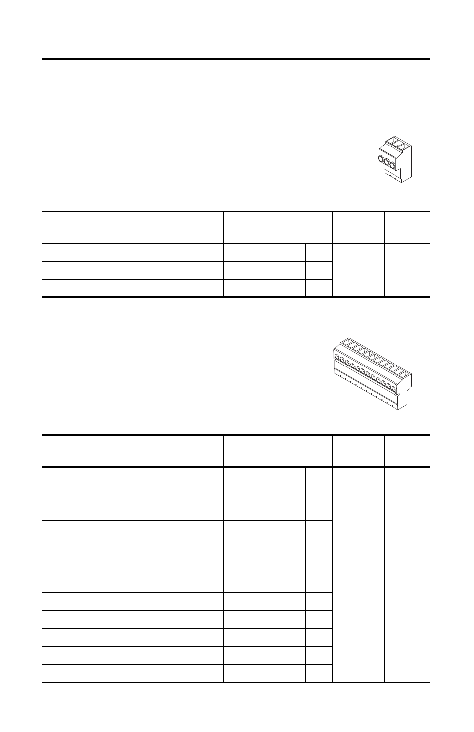
Hybrid Cable Communication Signals Connector
The hybrid communication connector extends control power,
communication, and safety signals to the first IDM unit. The
2090-CHBIFS8-12AA
xx cable interfaces with this connector.
Terminal
Description
Signal
Strip Length
mm (in.)
Torque
N•m (lb•in)
1
DC Bus Supply (-)
DC-
DC-
9.7 (0.38)
0.75 (6.6)
2
PE Ground
PE
PE
3
DC bus supply (+)
DC+
DC+
Terminal
Description
Signal
Strip Length
mm (in.)
Torque
N•m (lb•in)
1
Shield
–
–
6.4 (0.25)
0.235 (2.0)
2
Control Power +42V DC
42+
42+
3
Control Power -42V DC
42-
42-
4
CAN Bus Shield
IDM CAN SHIELD
SH2
5
IDM CAN Bus Lo
IDM CAN LO
CN-
6
IDM CAN Bus Hi
IDM CAN HI
CN+
7
System OK out to IDMs
IDM SYSOKOUT
OUT
8
System OK return from IDMs
IDM SYSOKRTN
RTN
9
Safety Shield
SAFETY SHIELD
SH3
10
Safety Enable Input 1
SAFETY ENABLE 1+
SE1
11
Safety Enable Common
SAFETY ENABLE-
SE-
12
Safety Enable Input 2
SAFETY ENABLE 2+
SE2
1
DC-
PE
DC+
1
Shield
42+
42-
SH2
CN-
CN+
OUT
RTN
SH3
SE1
SE-
SE2