Chapter 4 - multi-axis cascaded systems, Introduction, Cascaded configurations – Rockwell Automation 2094-EN02D-M01-S0 Kinetix 6200 and Kinetix 6500 Safe Torque-off Safety Reference Manual User Manual
Page 27: Chapter 4, Multi-axis cascaded systems, Chapter
Rockwell Automation Publication 2094-RM002B-EN-P - May 2012
27
Chapter
4
Multi-axis Cascaded Systems
Introduction
This chapter describes cascaded multi-axis drive operation and provides wiring
examples for cascaded multi-axis drive systems.
Cascaded Configurations
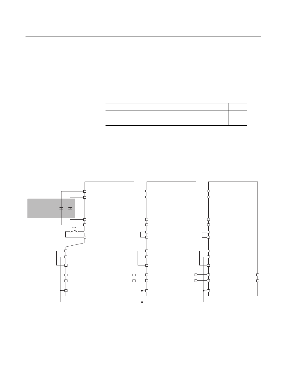
For cascaded drives, connect the safety switches to the safety inputs (SS_In) of
only the first axis. The inputs are cascaded from one drive to the next by
connecting the outputs from the previous drive to the inputs of the next drive.
Figure 12 - Cascaded Connections
Topic
Page
Reset
Test_Out_0 (IOD-27)
Test_Out_1 (IOD-28)
First Unit
Axis 1
SS_IN_CH2 (IOD-23)
SS_IN_CH3 (IOD-24)
24VPWR (IOD-14)
24VCOM (IOD-15)
SPWR (IOD-17)
SCOM (IOD-18)
SS_IN_CH1 (IOD-20)
SS_IN_CH0 (IOD-19)
Middle Unit
Axis 2
Last Unit
Axis 3
RESET_REF (IOD-25)
RESET_IN (IOD-26)
SS_IN_CH2
SS_IN_CH3
SS_IN_CH2
SS_IN_CH3
Test_Out_0
Test_Out_1
24VPWR
24VCOM
SPWR
SS_IN_CH1
SS_IN_CH0
RESET_REF
RESET_IN
(IOD-21) SS_OUT_CH0
(IOD-22) SS_IN_CH1
SS_OUT_CH0
SS_IN_CH1
SS_OUT_CH0
SS_IN_CH1
SCOM
SCOM
Test_Out_0
Test_Out_1
24VPWR
24VCOM
SPWR
SS_IN_CH1
SS_IN_CH0
RESET_REF
RESET_IN
Dual-channel
Equivalent
Safety Device