Install motor feedback cables – Rockwell Automation 2090-CFxxx 2090-Series Motor/Actuator Cable Installation Instructions User Manual
Page 9
Rockwell Automation Publication 2090-IN050B-EN-P - July 2014
9
2090-Series Motor/Actuator Cables
Install Motor Feedback Cables
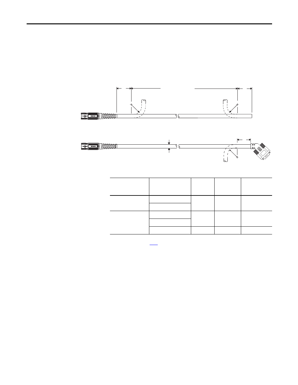
This figure illustrates how to measure the bend radius and where cable bends can
be made on motor feedback cables.
Figure 4 - Motor Feedback Bend Radius Examples
Table 6 - Feedback Cable Specifications
2090-CFBM7DD-
xxxxxx
B
B
B
D
Bend Area or
Continuous Flexing Area
Bend Radius
Bend Radius
Cable
Diameter
Bend Radius
2090-CFBM7DF-
xxxxxx
Cable Type
Cable Cat. No.
D
mm (in.)
B
(1)
mm (in.)
(1) Dimension B (static bend radius) and continuous bend radius are based on the cable diameter. See Motor Power and Feedback Cable
for more information.
Continuous
Bend Radius
mm (in.)
Feedback cables
(standard, non-flex)
2090-CFBM7DD-CEAA
xx
9.8 (0.39)
68.6 (2.7)
N/A
2090-CFBM7DF-CEAA
xx
Feedback cables
(continuous-flex)
2090-CFBM7DD-CEAF
xx
10.3 (0.40)
72.1 (2.8)
124 (4.9)
2090-CFBM7DF-CEAF
xx
2090-CFBM7DF-CDAF
xx
11.7 (0.46)
81.9 (3.2)
140 (5.5)