Install the right angle cables, Right-angle power/brake cables – Rockwell Automation 2090-CFxxx 2090-Series Motor/Actuator Cable Installation Instructions User Manual
Page 15
Rockwell Automation Publication 2090-IN050B-EN-P - July 2014
15
2090-Series Motor/Actuator Cables
Install the Right Angle Cables
Follow these steps to attach a right-angle cable connector to the motor connector.
1. Align all flat surfaces on the cable connector with the flat surface on the
motor connector.
2. Push the cable connector onto the motor connector to fully seat the
connection.
3. Twist the knurled front end of the cable connector clockwise
approximately 60° to secure the connection.
Right-angle Power/Brake Cables
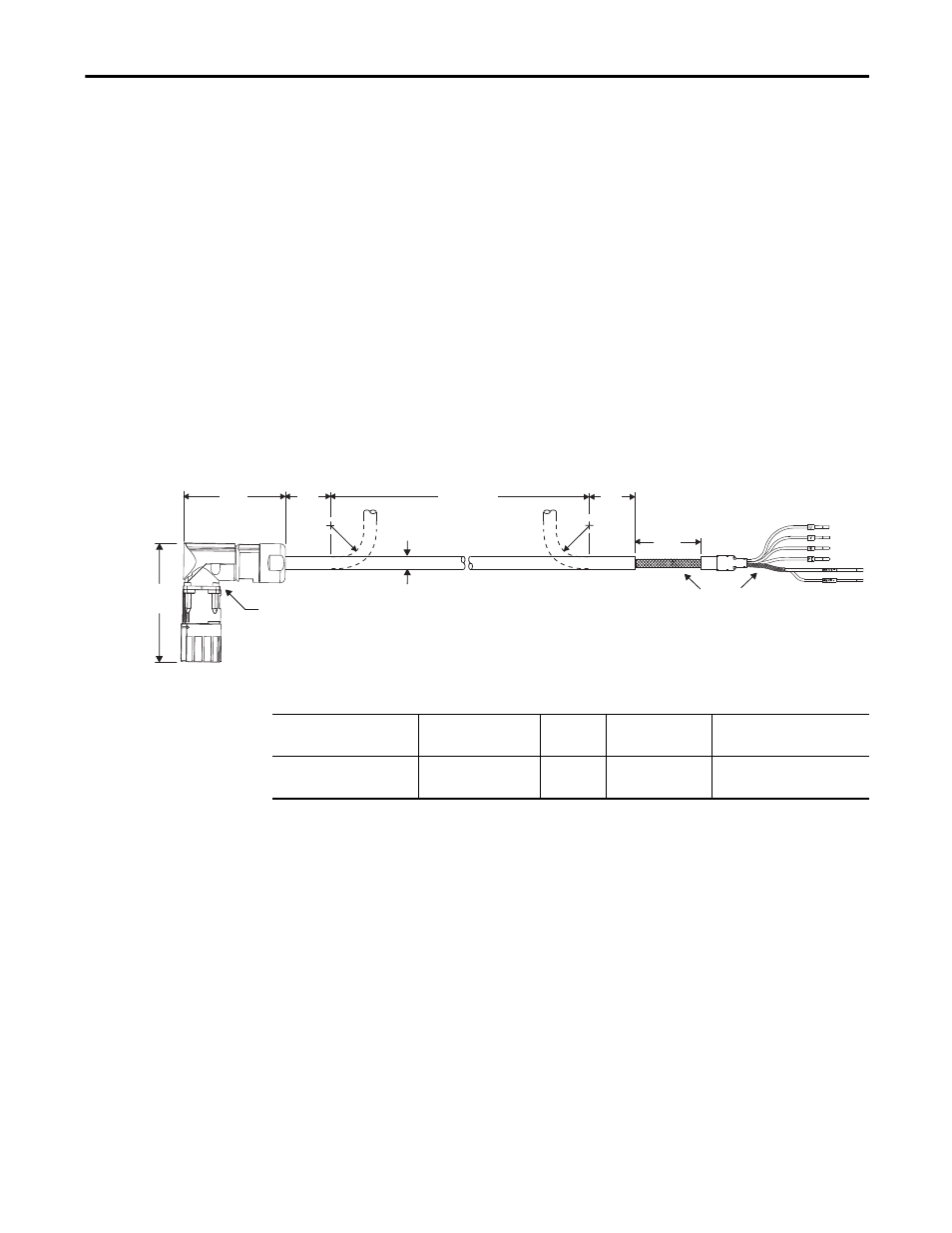
This figure illustrates how to measure the bend radius and where cable bends can
be made on right-angle power/brake cables.
Figure 6 - Right-angle Power/Brake Cable Bend Radius Example
Table 14 - Right-angle Power/Brake Cable Specifications
You can reposition right-angle power cables in 90° increments. Follow these steps
to reposition the power cable connector.
1. Remove the four 2 mm hex screws on the back of the cable connector.
2. Reposition the connector body to a new position by rotating the
connector 90°, 180°, or 270°.
3. Secure the two parts together with the four 2 mm hex screws.
Torque screws to 0.25 N•m (2.2 lb•in), maximum.
71.0
(2.8)
82.0
(3.2)
150
(5.9)
11.6
(0.46)
81.2
(3.2)
81.2
(3.2)
Bend Area
Cable
Diameter
Hex Screw (4x)
Cable
Shields
Power/Brake Cable Type
Cable Cat. No.
Wire Size
AWG
Available Lengths
mm (in.)
Connector IP Rating
Right-angle power/brake cable
(standard, non-flex)
2090-CPBM7DF-16RA
xx
16 (power)
18 (brake)
3, 6, 9, 15 m
(10, 16, 30, 49 ft)
IP54
(dust protected, splashing water)