Rockwell Automation 2090-CFxxx 2090-Series Motor/Actuator Cable Installation Instructions User Manual
Page 13
Rockwell Automation Publication 2090-IN050B-EN-P - July 2014
13
2090-Series Motor/Actuator Cables
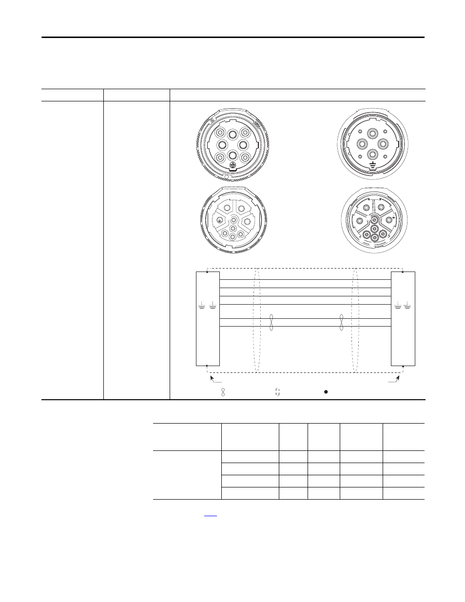
Extension Power Cable Pinout Diagrams and Specifications
Table 10 - Extension Power/Brake Cable Pinouts
Table 11 - Extension Power/Brake Cable Specifications
Extension Cable Type
Cable Cat. No.
Description
Extension power/brake
cable
(continuous-flex)
2090-CPBM7E7-16AF
xx,
2090-CPBM7E7-14AF
xx,
2090-CPBM7E7-10AF
xx,
2090-CPBM7E7-08AF
xx
C
B
A
E
F
H
L
C
B
A
F
U
V
W
U
V
W
A
B
C
A
B
C
F
G
E
H
L
F
G
E
H
L
MBRK+
MBRK-
MBRK+
MBRK-
+
–
1
2
+
–
1
2
V
V
–
–
W
W
2
2
1
1
U
U
+
+
G
G
L
E
H
2090-CPBM7E7-16AF
xx
2090-CPBM7E7-14AF
xx
2090-CPBM7E7-10AF
xx
2090-CPBM7E7-08AF
xx
Brown
Black
Blue
Green/Yellow
18 AWG White
18 AWG Black
Shield
Motor Plug
Extension Plug
Twisted Wire Pair
Connector Backshell Shielded 360°
Wire Connection
Shield
Connect Cable Shield to Ground
Cable Type
Cable Cat. No.
Wire Size
AWG
D
mm (in.)
B
(1)
mm (in.)
mm (in.)
Extension power/brake cables
(continuous-flex)
2090-CPBM7E7-16AF
xx 16
12.5 (0.49)
87.5 (3.4)
150 (5.9)
2090-CPBM7E7-14AF
xx 14
13.7 (0.54)
95.9 (3.8)
164 (6.4)
2090-CPBM7E7-10AF
xx 10
17.8 (0.70)
125 (4.9)
214 (8.4)
2090-CPBM7E7-08AF
xx 8
20.6 (0.81)
144 (5.7)
247 (9.7)
(1) Dimension B (static bend radius) and continuous bend radius are based on the cable diameter. See Motor Power and Feedback Cable Bend
for more information.