Install continuous-flex extension cables – Rockwell Automation 2090-CFxxx 2090-Series Motor/Actuator Cable Installation Instructions User Manual
Page 12
12
Rockwell Automation Publication 2090-IN050B-EN-P - July 2014
2090-Series Motor/Actuator Cables
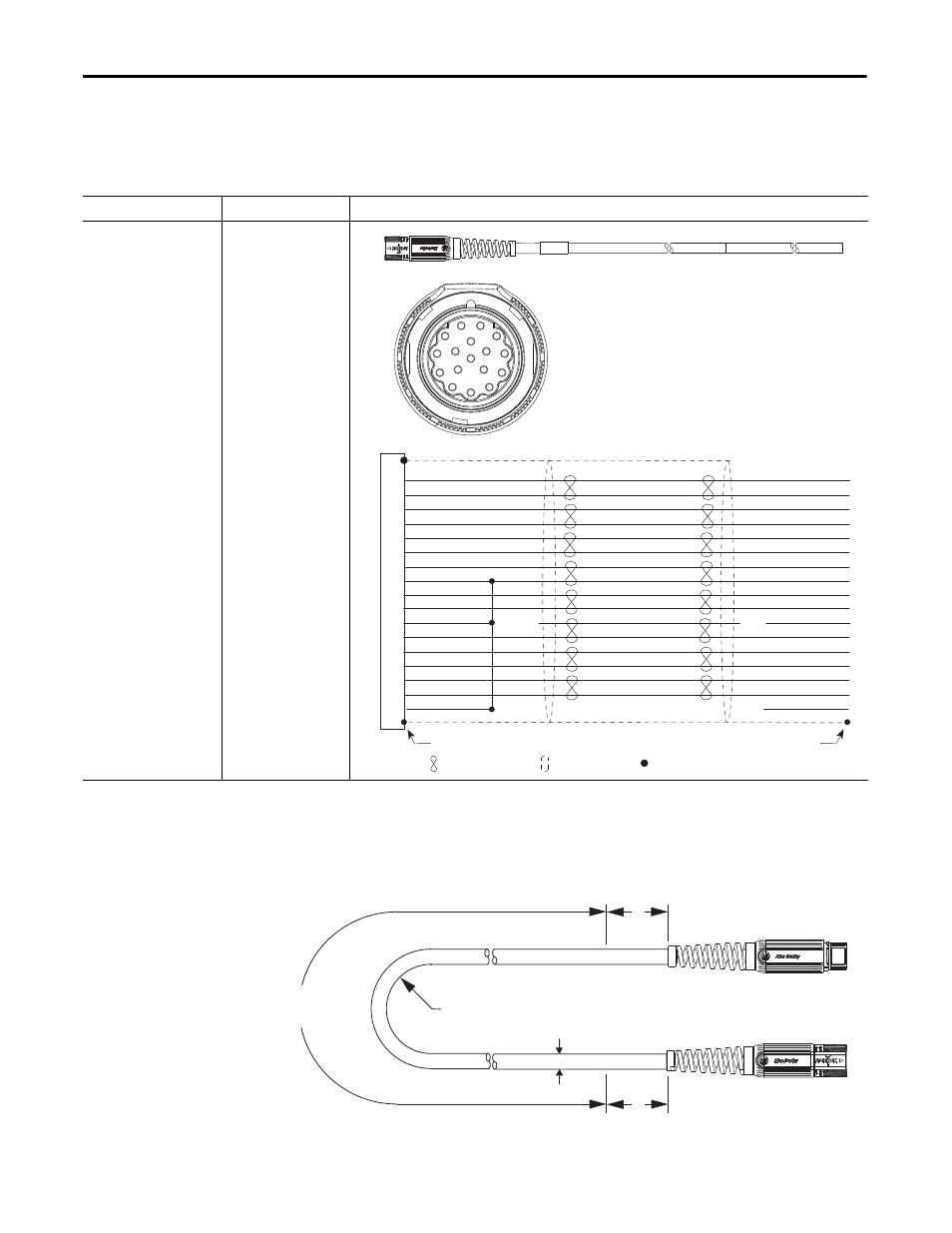
2090-CFBM7DF-CDAF
xx feedback cables (-CD designation) include Hall
signal conductors and are designed for motors with incremental encoders.
Table 9 - Feedback Cable Pinouts (flying-leads with Hall signals)
Install Continuous-flex
Extension Cables
This figure illustrates how to measure the bend radius and where cable bends can
be made on continuous-flex extension cables.
Figure 5 - Continuous-flex Extension Cable Bend Radius Example
Feedback Cable Type
Cable Cat. No.
Description
Feedback cable
(continuous-flex)
2090-CFBM7DF-CDAF
xx
N/C
N/C
1
2
3
4
5
6
9
10
11
13
14
15
16
17
7
8
12
SIN+/AM+
SIN-/AM-
COS+/BM+
COS-/BM-
DATA+/IM+
DATA-/IM-
EPWR 5V
ECOM
EPWR 9V
TS+
TS-
S1
S2
S3
Spare
ABS
ECOM
N/C
1
2
3
4
5
16
15
14
13
12
11
10
9
8
7
6
17
Twisted Wire Pair
Motor Plug
Connector Backshell Shielded 360°
Wire Connection
To Drive
Shield
Connect Cable Shield to Ground
26 AWG Black
26 AWG White/Black
26 AWG Red
26 AWG White/Red
26 AWG Green
26 AWG White/Green
16 AWG Gray
16 AWG White/Gray
22 AWG Orange
22 AWG White/Orange
26 AWG Blue
26 AWG White/Blue
26 AWG Yellow
26 AWG White/Yellow
26 AWG Brown
26 AWG White/Brown
36 AWG Shield
B
B
D
Bend Area or
Continuous Flexing Area
2090-CPBM7E7-
xxAFxx cable is shown.
Continuous
Bend Radius
Cable
Diameter