Parallel port timing requirements – Rockwell Automation 2706-DXX Dataliner Message Display DL5 Series User Manual
Page 77
2706-UM001A-US-P
Using the Variable Data Feature
9-5
Parallel Port Timing
Requirements
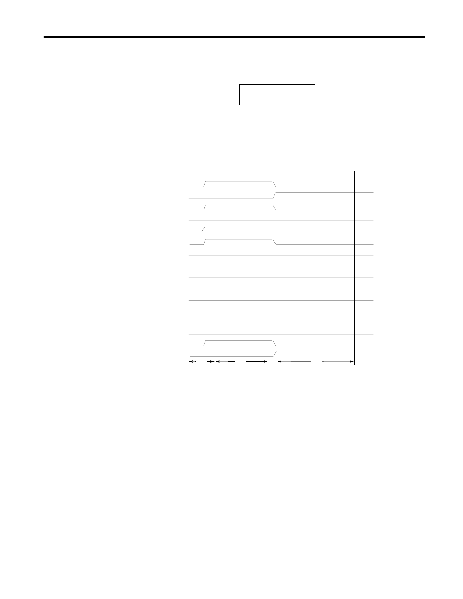
The following is an example of how the strobe commands are used. In this
example, message #12 , which contains a two digit variable, is triggered.
The message that was entered for message #12 appears like this:
First the controller sends the variable value (BCD format) for message #12
to the DL5. Then the controller sends the trigger for message #12. The
figure below illustrates the timing of the data transfer and message trigger.
The following describes what occurs during each of the timing intervals.
t0- During t0 the variable data 35 and strobe line D14 to indicate variable
data is set on the data lines.
t1- During t1 the value of 35 and strobe line D14 are maintained for 110
milliseconds.
t2- During t2 the message number 12 is placed on the data lines, and
D15 is set to indicate a message number. D14 is reset.
t3- During t3 the message number 12 and strobe line D15 are maintained
for 110 milliseconds.
The timing example (previous page) shows the minimum hold time (110
milliseconds) that is required for each step of the variable data
transfer and message trigger.
63((' ,6AA)36
BCD Message Number Timing Example
D0
D1
D2
D3
D4
D5
D6
D7
D8
D9
D10
D11
D12
D13
D14
D15
t0
t1
t2
t3
110 ms
110 ms