Rockwell Automation 61C350 2-In/2-Out 0-10 Volt Analog Rail Module User Manual
Page 30
4Ć8
4.1.3
AutoMate Programming in Local Head Mode
In Local Head mode, the module is imaged in four I/O registers of
the processor. Data from all four channels is always available and
will be updated at the end of each scan. For input channels, it is not
necessary to select the channel. After the I/O update, the register
contains the data in the format shown in figure 4.9. For output
channels, the data in the register must be in the format shown in
figure 4.10 prior to the I/O update.
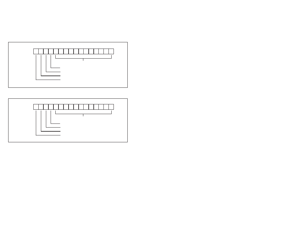
17 16 15 14 13 12 11 10 7 6 5 4 3 2 1 0
Octal
12 bits of converted analog data
overĆrange (1=overĆrange)
underĆrange (1=underĆrange)
not used
not used
Figure 4.9 Ć Local Head Register Image for Input Channels
17 16 15 14 13 12 11 10 7 6 5 4 3 2 1 0
Octal
12 bits of analog output data
not used
not used
not used
not used
Figure 4.10 Ć Local Head Register Image for Output Channels
The Analog Rail module data may also be accessed in the middle of
the scan (as opposed to the end of the scan) using the appropriate
number of Analog In (AIN) and Analog Out (AOUT) blocks. The AIN
block will set the overĆrange or underĆrange bits if applicable. See
section 4.1.4 for more information about the AIN and AOUTblocks.
Note that the AIN and AOUTblocks are supported by the AutoMate
20E M/N 45C224 and 45C225, but not the AutoMate 20 (M/N 45C20,
45C21, 45C220, 45C221) by APX Version 3.0.
For processors that do not support the AIN and AOUTblocks, you
can use the MOVE block to move data in and out of the registers
assigned. OverĆrange and underĆrange bits should be used as
inputs to error coils. The I/O update will occur automatically at the
end of each scan. See Appendix C for a sample AutoMate program
that writes to and reads from the Analog Rail module without using
AIN and AOUTblocks.