Rockwell Automation 61C350 2-In/2-Out 0-10 Volt Analog Rail Module User Manual
Page 29
4Ć7
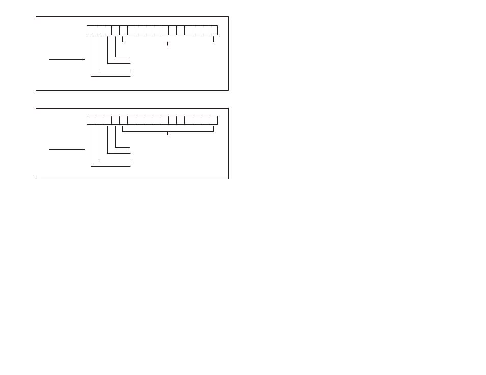
17 16 15 14 13 12 11 10 7 6 5 4 3 2 1 0
Octal
12 bits of converted analog data
overĆrange (1=overĆrange)
underĆrange (1=underĆrange)
channel being read: LSB
channel being read: MSB
MSB LSB ăCH#
ă0ąą0 = CH 0
ă0ąą1 = CH 1
ă1ąą0 = CH 2
ă1ąą1 = CH 3
Figure 4.7 Ć Rail Mode Register Image for Input Channels
17 16 15 14 13 12 11 10 7 6 5 4 3 2 1 0
Octal
12 bits of analog output data
not used
not used
channel being modified: LSB
channel being modified: MSB
MSB LSB ăCH#
ă0ąą0 = CH 0
ă0ąą1 = CH 1
ă1ąą0 = CH 2
ă1ąą1 = CH 3
Figure 4.8 Ć Rail Mode Register Image for Output Channels
The Analog Rail module data may also be accessed in the middle of
the scan (as opposed to the end of the scan, which is the normal
mode of operation for digital rail I/O) using the appropriate number
of Analog In (AIN) and Analog Out (AOUT) blocks. The AIN block
will check whether the overĆrange or underĆrange bits have been set
by the module and the error coil will be energized, if applicable. The
AOUT block will set the channel select bits appropriately. See
section 4.1.4 for more information about the AIN and AOUT blocks.
Note that the AIN and AOUT blocks are supported by the AutoMate
20E M/N 45C224 and 45C225, but not the AutoMate 20 (M/N 45C20,
45C21, 45C220, 45C221) by APX Version 3.0.
For processors that do not support the AIN and AOUT blocks, you
can use the MOVE block to move data in and out of the registers
assigned and to determine the channel select bits. OverĆrange and
underĆrange bits should be used as inputs to error coils. The I/O
update will occur automatically at the end of each scan. See
Appendix C for a sample AutoMate program that reads from and
writes to the Analog Rail module without using AIN and AOUT
blocks.