0 programming, 1 analog rail module in automate systems – Rockwell Automation 61C350 2-In/2-Out 0-10 Volt Analog Rail Module User Manual
Page 23
4Ć1
4.0 PROGRAMMING
This section describes how the data is organized in the module and
provides examples of how the module is accessed by application
programs.
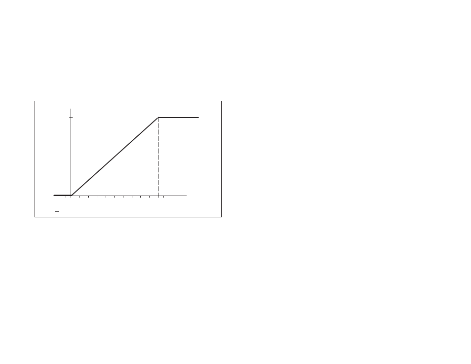
When creating application programs, the programmer should
estimate the magnitude of input signals and output data because
both must be in the specified range of the Analog Rail module
(0Ć10V). Input signals greater than 10V will be clamped at 4095.
Input signals greater than approximately 11.3V will also cause the
overĆrange bit (12 decimal; 14 octal) to be set to 1. Signals less than
0V are clamped at zero (0). Signals less than approximately -1V will
also cause the underĆrange bit (13 decimal; 15 octal) to be set to 1.
See figure 4.1.
Counts
4095
0
<-1 = underĆrange
>11.3V = overĆrange
Volts
1 2 3 4 5 6 7 8 9 10
Ć1
11
Figure 4.1 Ć Input Signal Conversion
Recall that at a digital output = 4096, the output rolls over to zero
again. The programmer must include limits in the application
software to ensure that the data sent to output channels is always in
the specified range (allowable range = 0 to 4095).
4.1
Analog Rail Module in AutoMate Systems
This section describes how the Analog Rail is used with AutoMate
systems. Local Head mode allows all four channels on the module
to be updated at the end of the scan (normal I/O update rate in this
configuration), or during the scan using AIN and AOUT blocks (see
section 4.1.4). Rail mode allows only one channel to be updated at
the end of the scan (normal I/O update rate in this configuration), or
all four channels to be updated during the scan if AIN and AOUT
blocks are used.