Rockwell Automation 61C350 2-In/2-Out 0-10 Volt Analog Rail Module User Manual
Page 14
2Ć4
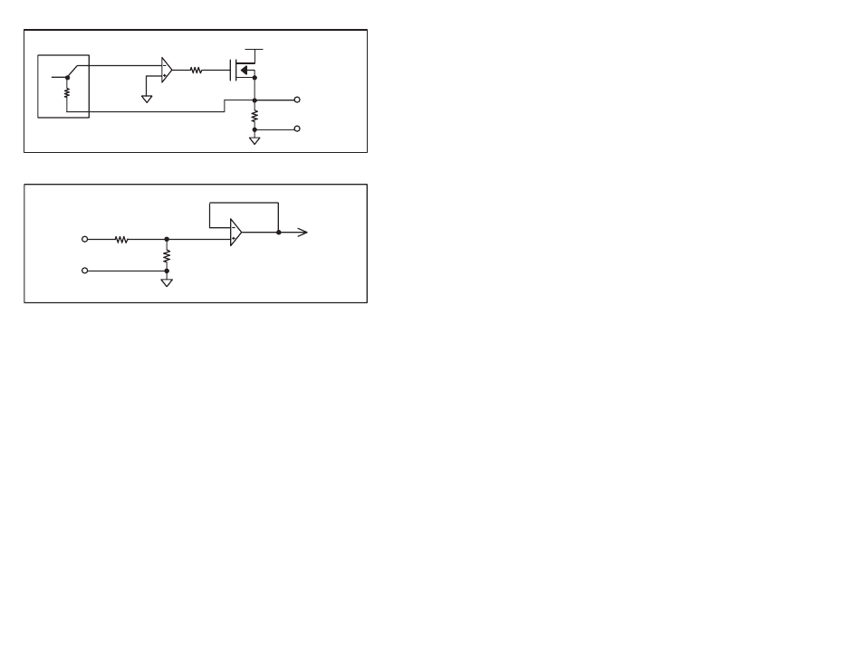
DAC
IĆOUT
RFB
+15V
+VĆOUT
-VĆCOMMON
10K
Figure 2.2 Ć Typical Output Circuit
4
to A/D
converter
VĆIN
VĆOUT
90K
90K
Figure 2.3 Ć Typical Input Circuit
The Analog Rail module is factory calibrated and requires no
offset/gain adjustment. All four analog I/Ochannels are referenced
to the same common. This common is isolated from both the
external power supply and the I/Oport connection.
The module incorporates extensive diagnostics. In Rail mode, check
bits are monitored for accuracy on every transfer of data between
the host and the module. In Local Head mode, parity bits are
monitored for accuracy on every transfer of data. A Rail fault LED on
the processor, Remote Head, or Local Head will be illuminated if the
check bits or parity bits are wrong and all transmission will stop after
n retries, where n is a value determined by the host's software
(average n = 4 for AutoMax; AutoMate n = 2).
In the event of a rail fault, all outputs will be set to 0. The COM OK"
LED on the module will go off. If any power required by the module,
i.e., the +5 Volts from the I/Oport required for communication, the
external power supply, or the power required by the Analog I/O
section, is not within specified limits, all outputs will be set to 0 and
the PWR OK" LED will go off.