Connect ground bus to grounding-electrode system – Rockwell Automation 1746-Ax SLC 500 Modular Chassis/ Instructions User Manual
Page 11
SLC 500™ Modular Chassis 11
Publication 1746-IN016C-MU-P - December 2003
Connect Equipment Grounding Conductor to Ground Bus
Connect an equipment grounding conductor directly from each chassis to an
individual bolt on the ground bus.
•
use 2.54 cm (1in) copper braid or 5.2 mm2 (10 AWG) copper wire to connect each chassis, the
enclosure, and a central ground bus mounted on the back-panel
•
use a steel enclosure to guard against electromagnetic interference (EMI)
•
make sure the enclosure door viewing window is a laminated screen or a conductive optical substrate
(to block EMI)
•
install a bonding wire for electrical contact between the door and the enclosure; do not rely on the
hinge
Connect Ground Bus to Grounding-Electrode System
The grounding-electrode system is at earth-ground potential and is the central
ground for all electrical equipment and ac power within any facility. Use a
grounding-electrode conductor to connect the ground bus to the
grounding-electrode system. Use at minimum 8.3 mm
2
(8 AWG) copper wire for
the grounding-electrode conductor to guard against EMI. The National Electrical
Code specifies safety requirements for the grounding-electrode conductor.
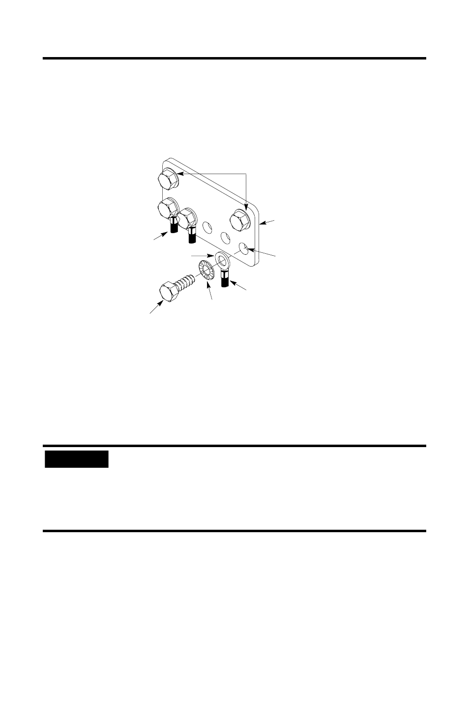
IMPORTANT
Do not lay one ground lug directly on top of the other; this type
of connection can become loose due to compression of the
metal lugs. Place the first lug between a star washer and a nut
with a captive star washer. After tightening the nut, place the
second lug between the first nut and a second nut with a captive
star washer.
bolt
equipment
grounding
conductors
ground
lug
star
washer
Grounding-electrode conductor
to grounding-electrode system
tapped hole
ground bus
ground bus mounting