Rockwell Automation 1747-DCM,D17476.8 Direct Communication Module User Manual
Page 51
Chapter 6
Programming
6–9
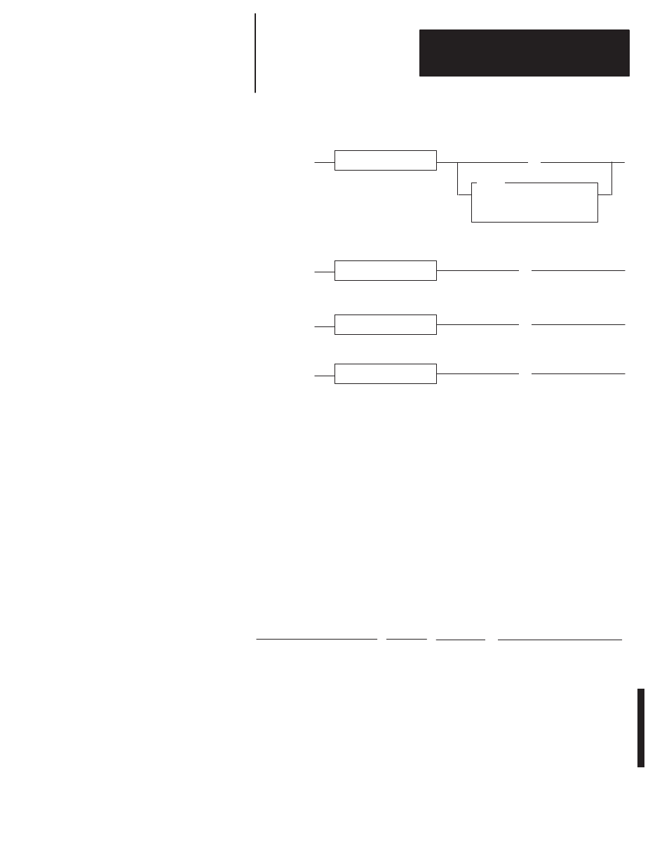
SLC Rungs
IOM
IMMEDIATE OUT w MASK
Slot
0:3.0
Mask
0800
Condition(s)
(L)
O:13.0
11
Set User Status Flag Bit
Condition(s)
Disable DCM
(U)
S2:11
03
➃
Condition(s)
Enable DCM
(L)
S2:11
03
Condition(s)
Clear User Status Flag Bit
(U)
O:3.0
➁
➁
➀
➀
➂
➃
11
➂
User Status Flag Bit
➀
Condition(s) to set User Status Flag bit is the same condition(s) to disable the DCM slot. When setting the
User Status Flag bit, an Immediate I/O (IOM) instruction must be used.
➁
Condition(s) to clear User Status Flag bit is the same condition(s) to enable the DCM slot.
➂
The SLC addresses this bit as bit 11 (decimal); the PLC-5 receives this bit as bit 13 (octal).
➃
S2:11-S2:12 – These two words are bit mapped to represent the 30 possible I/O slots in an SLC system.
S2:11/0 represents I/O slot 0 up through S2:12/14 which represents slot 30. S2:12/15 is unused.
After programming the SLC to set and clear the User Status Flag bit, this bit
can be used to condition any PLC-5 output in this example whose state is
dependent upon the data from the distributed SLC being valid.
PLC-5 Rung
] [
I:021
00
]/[
I:020
13
( )
O:000
00
The PLC-5 rung uses data from the DCM (word 1, bit 0) to energize PLC-5
output 0. It is conditioned on the User Status Flag bit being cleared. If the
SLC is programmed to set the User Status Flag bit prior to disabling the
DCM slot, the PLC-5 will never energize output 0 when data from the SLC
is invalid. For more information on how to enter PLC ladder logic, see your
PLC-5 programming manual.