3 - addressing, Addressing ladder logic instructions, Chapter 3 – Rockwell Automation 1747-DCM,D17476.8 Direct Communication Module User Manual
Page 25: Addressing, Chapter, Logical rack or physical slot address, Logical group or word address
3
Chapter
3–1
Addressing
This chapter provides general information about how to address supervisory
PLC and distributed SLC ladder logic instructions. It also illustrates image
mapping and provides an example of how a PLC output image is mapped
into an SLC input image.
All PLC and SLC processors use 3-part addresses. These three parts include:
•
logical rack or physical slot address
•
logical group or word address
•
bit address
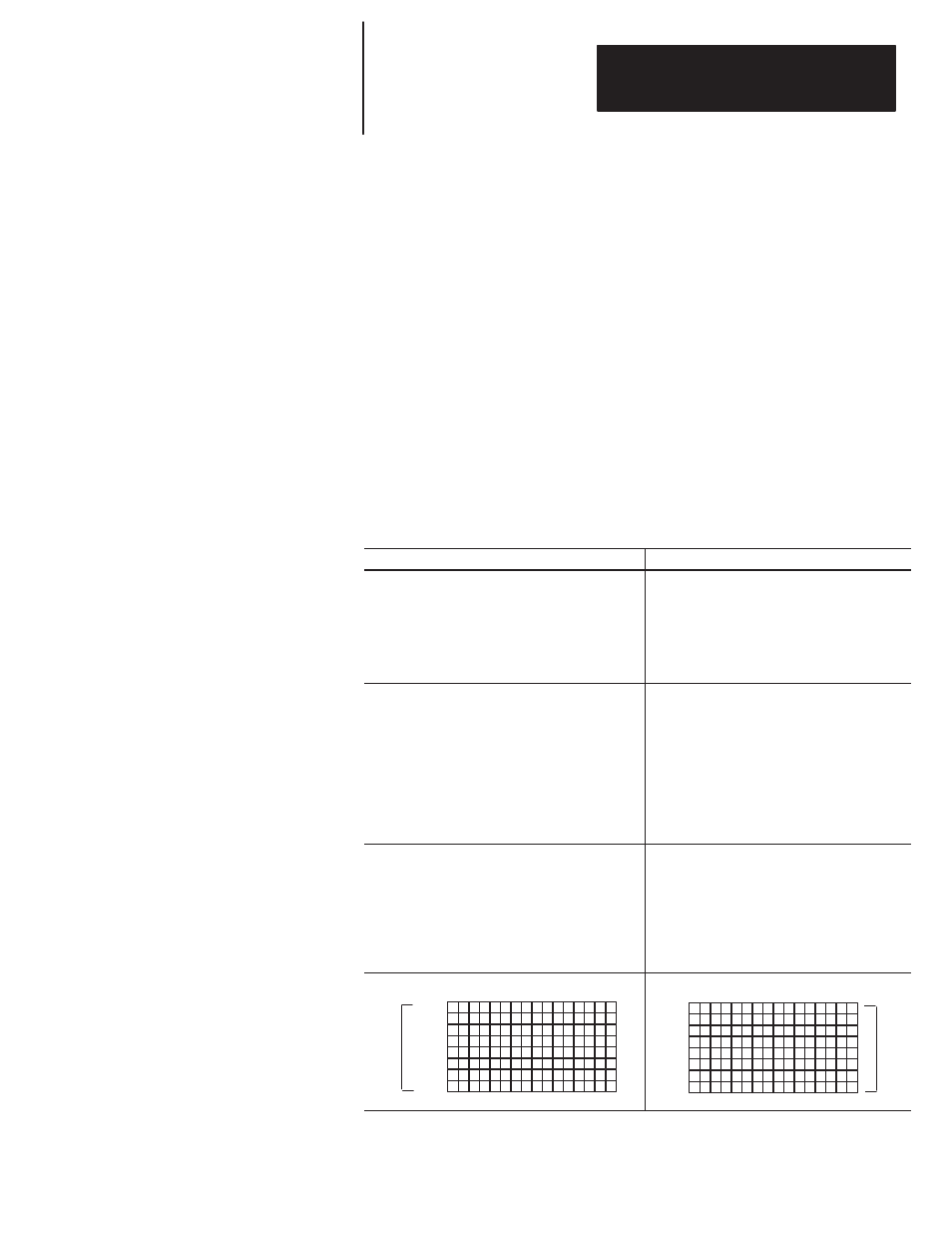
PLC processors use the octal number system for bit addressing. SLC
processors use the decimal number system for bit addressing.
PLC Processors/Scanners Address By:
SLC Processors Address By:
Logical Rack: PLC/scanner input and output
images are organized in logical
racks, which consist of eight
groups.
The rack address does not need to
match the SLC slot address.
Physical Slot: The slot address is determined
by what slot number you place
your DCM. SLC slots are
numbered 0–30.
The slot address does not need
to match the PLC rack address.
Logical Group: There are eight logical groups per
logical rack, numbered 0–7. One
group consists of one input and one
output word. Each word is made
up of 16 bits.
The group number does not need
to match the SLC word address.
Word: One word is 16 bits in size. The
number of words used in input
and output images varies
according to how many you
specify in your setup. Words are
numbered consecutively
beginning with 0.
The word number does not need
to match the PLC group number.
Bit: PLC bits are numbered octally, from
0 to 7 and 10 to 17.
The bit number does not need to
match the SLC bit number
(because SLCs use decimal);
however, the position of the bit in
the word must be the same.
Bit: SLC bits are numbered
decimally, from 0–15.
The bit number does not need to
match the PLC bit number
(because PLCs use octal);
however, the position of the bit in
the word must be the same.
Bit Number 17 16 15 14 13 12 11 10 7
6
5
4
3
2
1
0
Group 0
Group 1
Group 2
Group 3
Group 4
Group 5
Group 6
Group 7
Logical
Rack
#x
Octal
Bit Number 15 14 13 12 11 10 9
8
7
6
5 4
3
2
1
0
Word 0
Word 1
Word 2
Word 3
Word 4
Word 5
Word 6
Word 7
Physical
Slot
#x
Decimal
Addressing Ladder Logic
Instructions