Install the keying bands, Insert or remove keys with your fingers – Rockwell Automation 1771-OFE Analog Output Module Installation Instructions User Manual
Page 8
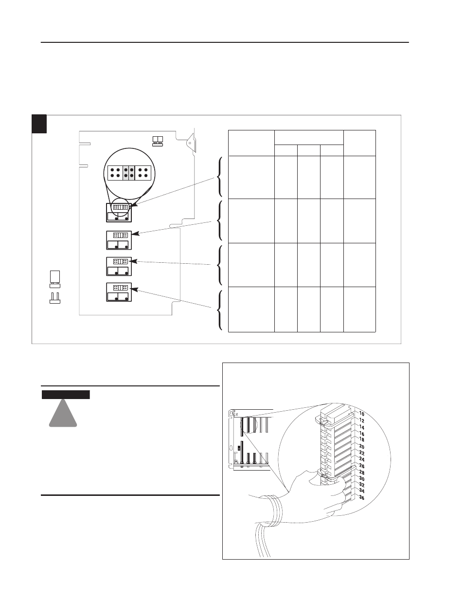
Place the keying bands:
between 10 and 12
between 26 and 28
Position the keying bands in the backplane connectors to
correspond to the key slots on the module.
You can change the position of these bands if
subsequent system design and rewiring makes
insertion of a different type of module necessary.
Upper
Connector
I/O chassis
Analog Output Module
8
Publication 1771-IN044C-EN-P - October 2002
Set the Voltage Range Configuration Jumpers (1771ĆOFE1 only)
If you ordered the voltage output version, you must set several
configuration jumpers located inside the module on the circuit board.
2
In
Out
In
In
Out
Out
Out
Out
0-10V
+-
Out
Out
In
In
Out
Out
1-5V
Out
Out
Out
Out
In
In
10V
1
2
3
4
In
In
Out
Out
Out
Out
Out
Out
In
In
Out
Out
Out
Out
Out
Out
In
In
In
In
Out
Out
Out
Out
Out
Out
In
In
Out
Out
Out
Out
Out
Out
In
In
In
In
Out
Out
Out
Out
Out
Out
In
In
Out
Out
Out
Out
Out
Out
In
In
LAST STATE
(side view
of jumper)
Configuration
Jumper
Location
Locate the configuration jumpers and set them according to your output voltage requirements.
Desired Voltage Range
Output
Channel
P3, Jumper
P5, Jumper
P7, Jumper
P9, Jumper
1
11
1-2
3-4
5-6
7-8
9-10
11-12
1-2
3-4
5-6
7-8
9-10
11-12
1-2
3-4
5-6
7-8
9-10
11-12
1-2
3-4
5-6
7-8
9-10
11-12
12
2
!
ATTENTION
Observe the following precautions
when inserting or removing keys:
•
Insert or remove keys with your
fingers.
•
Make sure the key placement is
correct
Incorrect keying or the use of a tool
can result in damage to the
backplane connector and possible
system faults.
Install the Keying Bands