Configure the module – Rockwell Automation 1771-OFE Analog Output Module Installation Instructions User Manual
Page 12
Analog Output Module
12
Publication 1771-IN044C-EN-P - October 2002
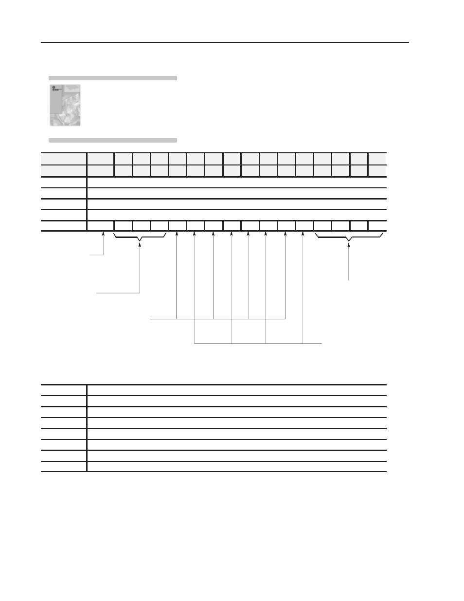
Because of the many analog devices available and the wide variety
of possible applications, you must configure the module to conform
to the analog device and specific application that you have chosen.
Use the configuration information below to configure your module
to your specifications.
Word/Dec. Bit
15
14
13
12
11
10
09
08
07
06
05
04
03
02
01
00
Word/Octal Bit
17
16
15
14
13
12
11
10
07
06
05
04
03
02
01
00
1
Channel 1 Data Value
2
Channel 2 Data Value
3
Channel 3 Data Value
4
Channel 4 Data Value
Word 5
4
4
3
3
2
2
1
1
4
3
2
1
Data Format
Reserved
1 = Binary
0 = BCD
Maximum Scaling Value Polarity
1 = Negative
0 = Positive
Minimum Scaling Value Polarity
1 = Negative
0 = Positive
Data Sign Polarity
1 = Negative
0 = Positive
4 = Channel 4
3 = Channel 3
2 = Channel 2
1 = Channel 1
Module Default Configuration:
Data Format - BCD
No Scaling
Data Sign Polarity - Positive
6
Channel 1 Minimum Scaling Value
7
Channel 1 Maximum Scaling Value
8
Channel 2 Minimum Scaling Value
9
Channel 2 Maximum Scaling Value
10
Channel 3 Minimum Scaling Value
11
Channel 3 Maximum Scaling Value
12
Channel 4 Minimum Scaling Value
13
Channel 4 Maximum Scaling Value
For detailed configuration
information, see chapter 2
of your Analog Output User
Manual (publication
1771ĆUM030).
Configure the Module