Rockwell Automation 1771-OFE Analog Output Module Installation Instructions User Manual
Page 5
Analog Output Module
5
Publication1771-IN044C-EN-P - October 2002
Place your module in any I/O module slot of the I/O chassis except
for the left-most slot. This slot is reserved for PC processors or
adapter modules.
!
ATTENTION
Group your modules to minimize adverse affects
from radiated electrical noise and heat. We
recommend the following.
•
Group analog output and low voltage dc
modules away from ac modules or high voltage
dc modules to minimize electrical noise
interference.
•
Do not place this module in the same I/O group
with a discrete high-density I/O module when
using 2-slot addressing.
•
Limit adjacent slot power dissipation to 10W
maximum.
The module configuration jumpers consist of:
•
the last state configuration jumper (all versions)
•
the voltage range configuration jumpers (1771-OFE1 only).
The type of module you have dictates how you set the configuration
jumpers.
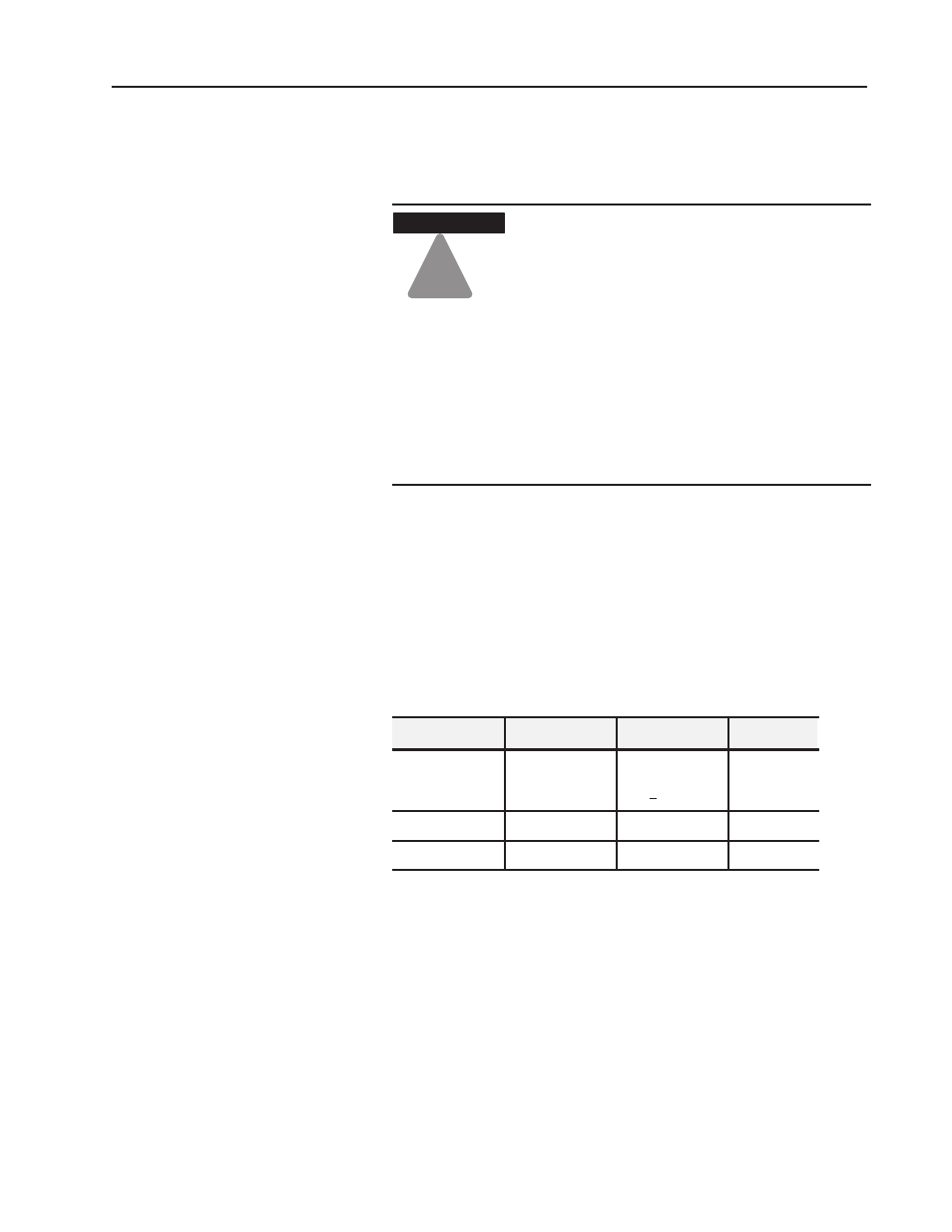
There are three versions of the analog output module:
Catalog Number
Module Output
Output Range
1771ĆOFE1
Voltage
1Ć5V dc
0Ć10V dc
+10V dc
Selected by
configuration
jumpers
1771ĆOFE2
Current
4Ć20mA
Factory set
1771ĆOFE3
Current
0Ć50mA
Factory set
Current Output Versions of the Module
Current version modules (1771-OFE2 and -OFE3) have all
configuration jumpers installed and require no additional
configuration. The configuration jumper for the LAST STATE mode
output level is in the default position (MID). Refer to the section
entitled “Set the Last State Configuration Jumpers” for additional
configuration information.
Determine Module
Placement in the I/O
Chassis
Set the Module
Configuration Jumpers