External module features – Rockwell Automation 1771-SDN DeviceNet Scanner Module Installation Instructions User Manual
Page 6
Publication 1771-IN014B-EN-P - September 2001
6 DeviceNet Scanner Module Catalog Number 1771-SDN/C
External Module
Features
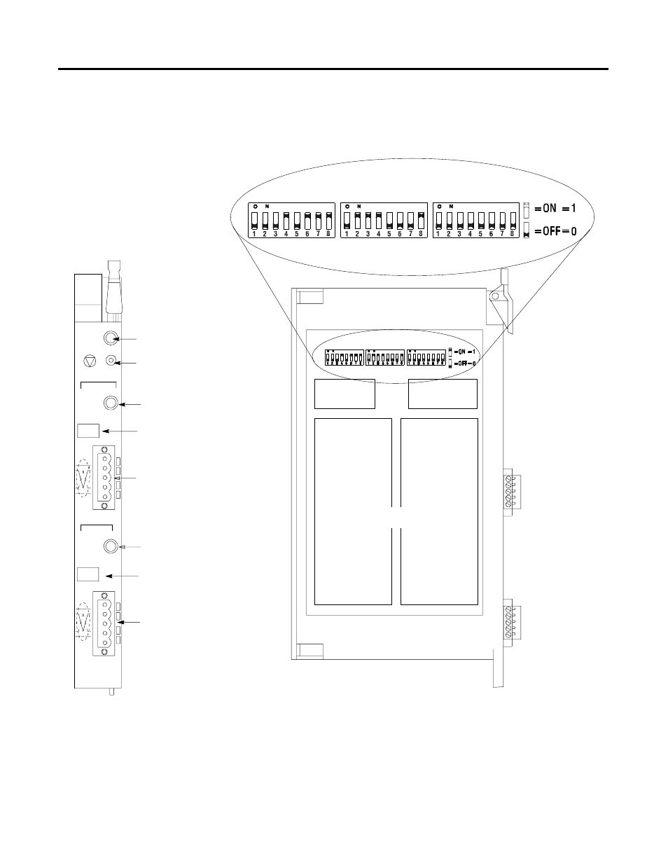
Use the drawing below to identify the features of the 1771-SDN/C and
B versions of the Scanner Module.
DeviceNet Port 1 - use the color-coded
header to wire your module.
20274
20275
Module Status Indicator - indicates
whether the device has power and
is functioning properly
Channel 1 Status Indicator - gives
diagnostic indications for Channel 1.
Reset Button - resets your module.
Node Address and Status Display -
displays numeric codes that indicate
scanner node address, status and/or
errors for Channel 1.
Channel 2 Status Indicator - gives
diagnostic indications for Channel 2.
Multi-position Switches-
use to set the data rate, chassis addressing mode
and scanner node address for each channel.
Front of Module
Left Side of Module
DeviceNet Port 2 - use the
color-coded header to wire your
module.
Data Rate
Switch Settings
Chassis Address
Switch Settings
Channel 1 & 2
Node Address Switch Settings
Node Address and Status Display -
displays numeric codes that indicate
scanner node address, status and/or
errors for Channel 2.
MODULE
STATUS
RESET
CHANNEL 1
NETWORK
STATUS
NODE/
ERROR CODE
DeviceNet
CHANNEL 2
NETWORK
STATUS
NODE/
ERROR CODE
DeviceNet
1771-SDN
CHANNEL 1
CHANNEL 2
CONFIGURATION
Allen-Bradley