Rockwell Automation 1771-SDN DeviceNet Scanner Module Installation Instructions User Manual
Page 23
Publication 1771-IN014B-EN-P - September 2001
DeviceNet Scanner Module Catalog Number 1771-SDN/C 23
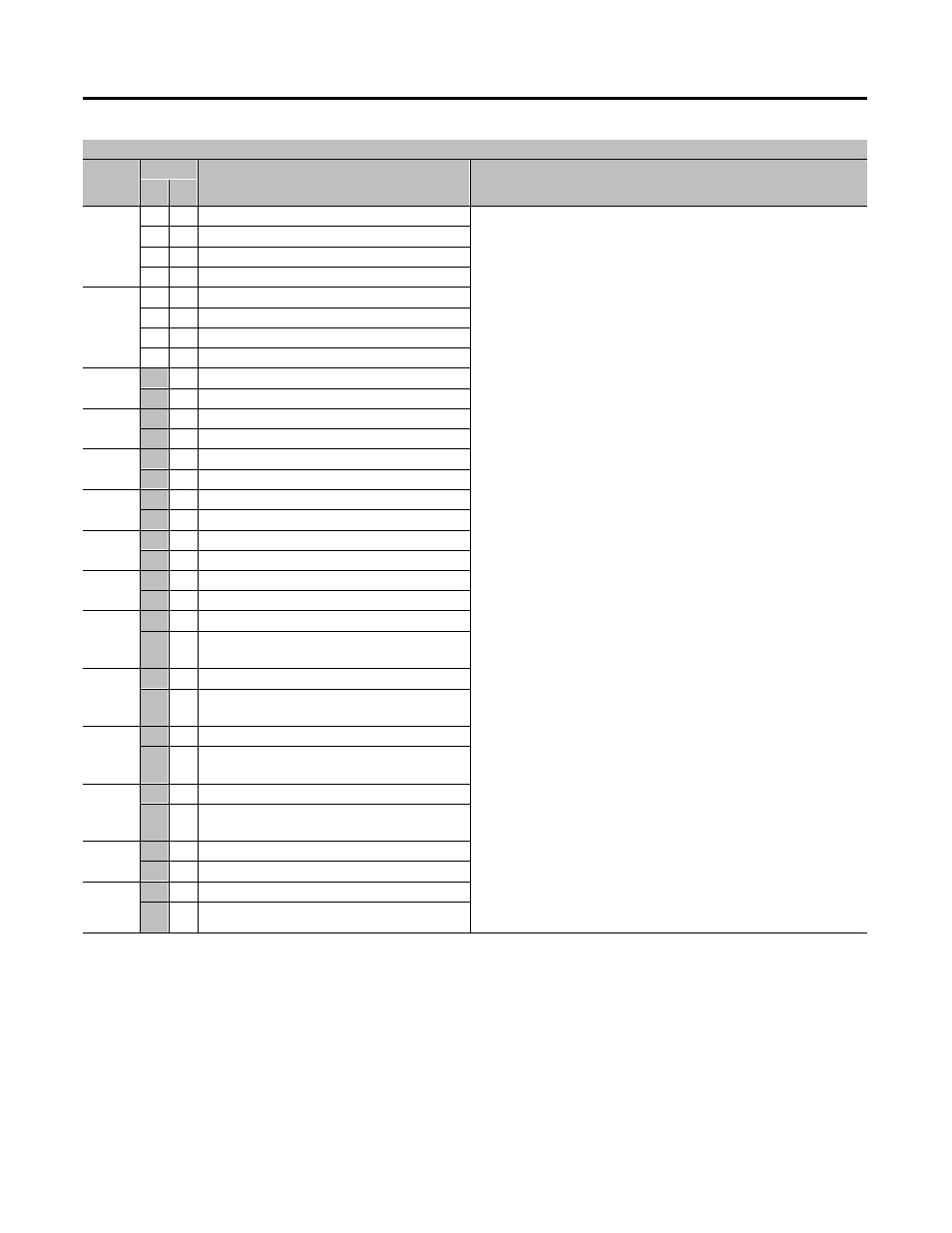
Module Status Register - Word 0, Block 62
Bit
Number
Bits
Operating Mode
Operating Mode Description
01
00
00 - 01
0
0
DeviceNet Channel 1 in idle mode
Idle
The scanner does not map output data to the devices, but keeps network
connections to devices open so device failures can be detected. Input data
is returned from devices, and mapped into the scanner input table and the
discrete inputs. Outputs on the network are not under program control and
will be in their configured ‘safe state.’ The scanner must be in this mode to
perform configuration of the scanner database tables.
Run
The scanner module maps output data from its scanner output table and
discrete outputs to each device on the network. Inputs are received and
mapped into the scanner input table and discrete inputs. Outputs on the
network are under program control.
Placing the PLC-5 into the PROG or REM_PROG mode places the scanner
into IDLE MODE regardless of the state of the bits in the module command
register. Placing the PLC-5 into RUN or REM_RUN mode causes the state
of the bits in the module command register to determine the scanner state.
Fault
The scanner has stopped communicating with devices on the network.
No outputs or inputs are mapped. Outputs on the network are not
under program control. If the scanner was in run, devices will go to their
fault state.
Device Failure
One or more of the devices in the scanner’s scan list has failed to
communicate with the scanner.
Autoverify Failure
One or more of the devices in the scanner’s scan list is returning an
incorrect number of bytes of data in response to a strobe/poll, according to
the information stored in the scanner’s scan list.
Communications Failure
There is no communication on the port.
Duplicate Node Address Failure
There is another node with the same address on the network.
Scanner Configuration Missing or Corrupted
Either the I/O chassis addressing mode is set to an illegal position or, the
chassis addressing mode switch does not match the value stored in the
scanner’s scan list.
Client/server transaction response queued
The client/server response is loaded and available with a 64-word Block
Transfer Read.
0
1
DeviceNet Channel 1 in run mode
1
0
DeviceNet Channel 1 in fault mode
1
1
Reserved
02 - 03
0
0
DeviceNet Channel 2 in idle mode
0
1
DeviceNet Channel 2 in run mode
1
0
DeviceNet Channel 2 in fault mode
1
1
Reserved
04
0
Enable DeviceNet Channel 1
1
Disable DeviceNet Channel 1
05
0
Enable DeviceNet Channel 2
1
Disable DeviceNet Channel 2
06
0
No failures detected
1
DeviceNet Channel 1 device failure detected
07
0
No failures detected
1
DeviceNet Channel 2 device failure detected
08
0
No failures detected
1
DeviceNet Channel 1 autoverify failure detected
09
0
No failures detected
1
DeviceNet Channel 2 autoverify failure detected
10
0
No failures detected
1
DeviceNet Channel 1 communications failure
detected
11
0
No failures detected
1
DeviceNet Channel 2 communications failure
detected
12
0
No failures detected
1
DeviceNet Channel 1 duplicate node address
failure
13
0
No failures detected
1
DeviceNet Channel 2 duplicate node address
failure
14
0
No failures detected
1
Scanner configuration missing or corrupted
15
0
No failures detected
1
Client/server transaction response queued