Install your module into the chassis – Rockwell Automation 1771-SDN DeviceNet Scanner Module Installation Instructions User Manual
Page 13
Publication 1771-IN014B-EN-P - September 2001
DeviceNet Scanner Module Catalog Number 1771-SDN/C 13
Install Your Module into
the Chassis
Before you insert the module into the chassis, set all switches in
accordance with the requirements of your networks. You must set the
switches before you install the the 1771-SDN Scanner Module or it will
not function properly.
1. Select a slot for the module in the chassis. You may use any slot
except the leftmost slot, which is reserved for the PLC processor.
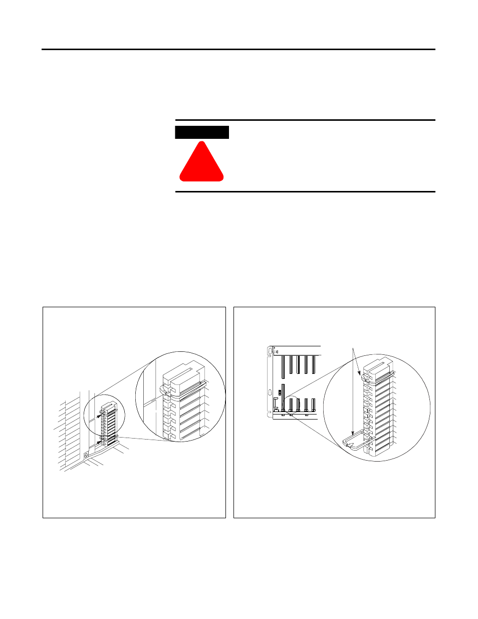
2. Adjust the chassis’ keying bands (see figures below).
The 1771-SDN Scanner Module uses keying bands to prevent
placing modules into the wrong slot. You can key any connector
in an I/O chassis to receive the module except for the leftmost
connector, which is reserved for adapter or processor modules.
WARNING
!
WARNING
!
If you insert or remove the scanner module with
power applied to this module or any device on the
network, an electrical arc can occur. This could
cause an explosion in hazardous location
installations. Be sure that power is removed or the
area is nonhazardous before proceeding.
keying bands
Position the keying bands in the backplane connectors to
correspond to the key slots on the module.
19808
Place the keying bands:
between 2 and 4
between 22 and
The 1771-SDN Scanner Module is slotted in two places on the
rear edge of the circuit board. These slots are intended to
mate with the plastic keying bands supplied with the I/O
chassis.
You can change the position of these bands if subsequent system design and
rewiring makes insertion of a different type of module necessary.
I/O chassis
Scanner module
I/O chassis
backplane connector
2
4
6
8
10
12
14
16
18
20
22
24
26
28
2
4
6
8
10
24