Set the data rate switches for channels 1 and 2, Set the i/o chassis addressing mode switches – Rockwell Automation 1771-SDN DeviceNet Scanner Module Installation Instructions User Manual
Page 10
Publication 1771-IN014B-EN-P - September 2001
10 DeviceNet Scanner Module Catalog Number 1771-SDN/C
Set the Data Rate Switches
for Channels 1 and 2
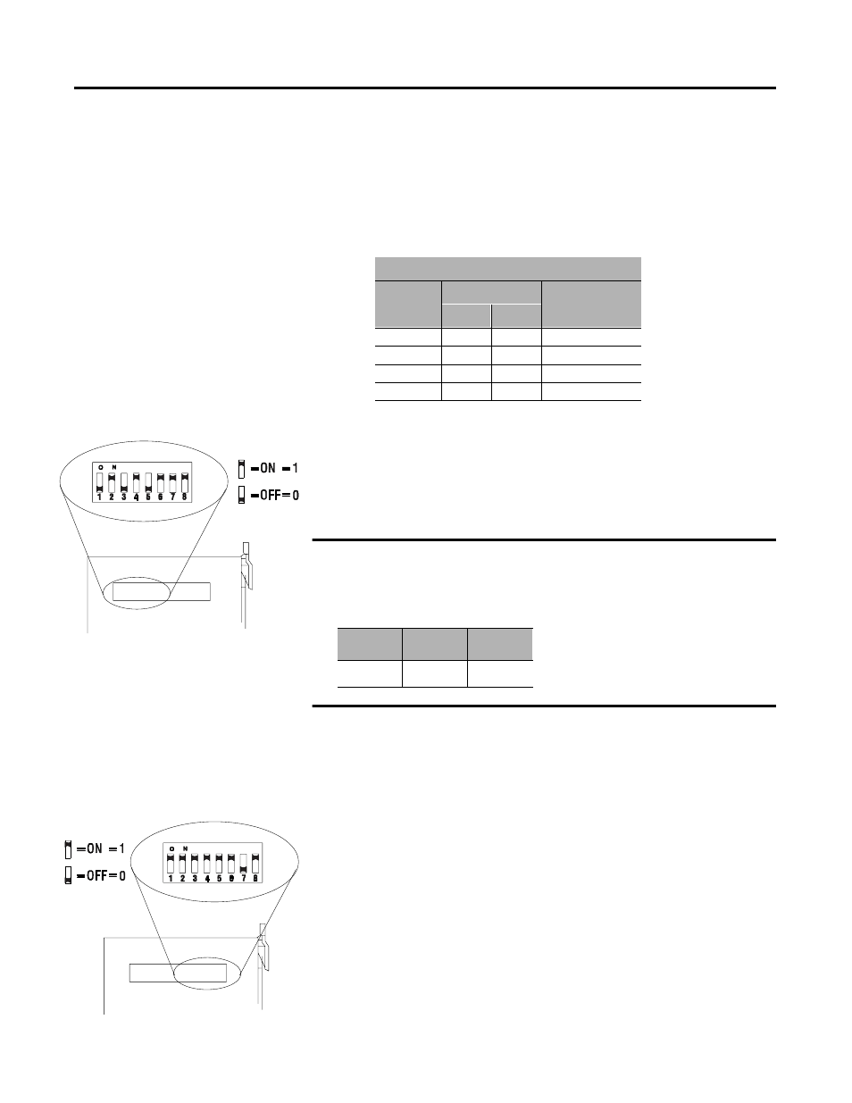
To set the DeviceNet data rate switches for Channels 1 and 2:
1. Locate the switchbank labeled “Channel 1” on the left side of the
module.
2. Use the table below to determine the data rate you want to set
for “Channel 1.” Record your choice in the fourth column.
3. Using a ball point pen or similar object, adjust switches 2 and 1
to your desired data rate setting. (NOTE: Do not use a pencil
to adjust switches. The lead may break off in the
switchbank.) Slide the switches up to denote an on or “1”
position. Slide the switches down to denote an off or “0”
position.
For example, if you want to set DeviceNet data rate of 500K baud for
Channel 1, then you set switch 2 to an off or “0” position and switch 1
to an on or “1” position.
4. Repeat steps 1-3 to set the DeviceNet data rate for Channel 2,
using the switchbank labeled “Channel 2’. Adjust the switches to
your desired data rate setting.
Set the I/O Chassis
Addressing Mode Switches
To set the I/O chassis addressing mode switches:
1. Locate the switchbank labeled “Configuration” on the left side of
the module.
2. Use the following table to determine the chassis addressing
mode you want to set. Record your choice in the fourth column.
Channel 1 and 2
Data Rate
Switch Position
Note Your
Data Rate
1
2
125K baud
0
0
250K baud
0
1
500K baud
1
0
Not allowed
1
1
Data Rate
Sw.1
Sw.2
500K
1
0
Data Rate
20276
Channel 1
Configuration
20277
Chassis Address