Logical continuity – Rockwell Automation 1747-PTxx Getting Started Guide for HHT User Manual
Page 24
Chapter 2
Control Basics
Getting Started Guide
for HHT
2–7
Logical Continuity
During controller operation, the processor evaluates each rung, changing the
status of instructions according to the logical continuity of rungs. More
specifically, input instructions set up the conditions under which the
processor will make an output instruction true or false. These conditions are:
•
When the processor finds a continuous path of true input instructions in a
rung, the OTE output instruction will become (or remain) true. We then
say that “rung conditions are true.”
•
When the processor does not find a continuous path of true input
instructions in a rung, the OTE output instruction will become (or remain)
false. We then say that “rung conditions are false.”
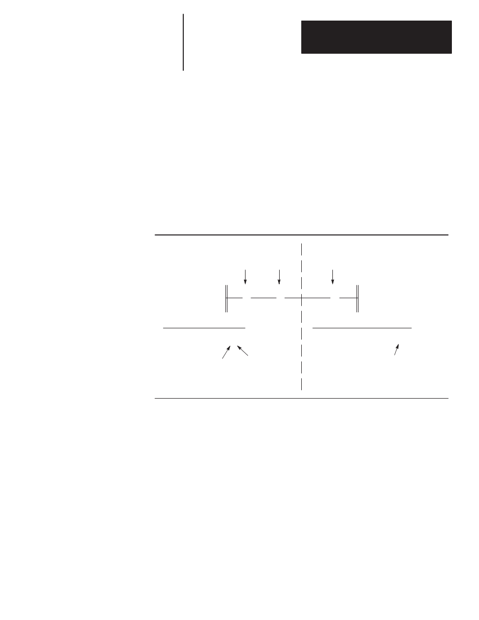
The figure below indicates the data file conditions under which the rung is
true:
Input Data File
address data
I:1 0001
Status bit I:1/0 is a
logic 1, making the
XIC instruction true.
Output Data File
address data
O:3 0000 0001
XIC
( )
O:3.0
0
] [
I:1.0
0
]/[
I:1.0
1
XIO
OTE
Input Instructions
Output Instruction
Status bit I:1/1 is a
logic 0, making the
XIO instruction true.
The processor changes status bit O:3/0 to
a logic 1, because a continuous path of
true input instructions exist in the rung.
In the above example, if the input data file was 0000, then the rung would be
false and the output data file would read as 0000 0000.