Rockwell Automation 1747-PTxx Getting Started Guide for HHT User Manual
Page 20
Chapter 2
Control Basics
Getting Started Guide
for HHT
2–3
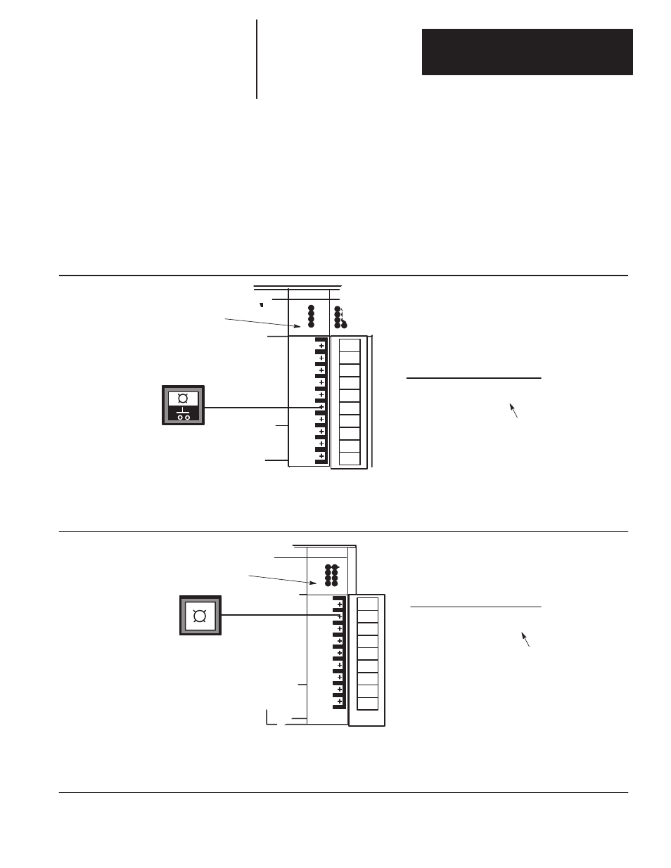
The figure below applies to a modular controller demo unit having an input
module in slot 1 and an output module in slot 3. See page 1–2 for a diagram
of the slot location. To simplify the illustration, only pushbutton 0 and pilot
light 0 of the external I/O are shown.
Each of the external input circuits is represented by a status bit in the input
data file of the program. Each of the external output circuits is represented
by a status bit in the output data file of the program. During controller
operation, the processor applies the input data to the program, solves the
program based on the instruction you enter, and energizes and de–energizes
external outputs.
SLC 5/01 CPU
INPUT
INPUT
IN 0
INPUT
IN 1
IN 2
IN 3
F8
0
Input Data File
address data
I:1 0000
Input Module
in slot 1
Status bit 0
corresponds to
terminal 0 of the
input module in
slot 1.
Pushbutton 0 is wired to terminal 0.
Pressing pushbutton 0 will cause
the corresponding status bit in the
input data file to go from 0 to 1.
Closing an external input circuit changes the corresponding status bit from 0 to 1.
Opening an external input circuit changes the corresponding status bit from 1 to 0.
OUTPUT
OUT 0
OUT 1
OUT 2
OUT 3
OUT 4
OUT 5
OUT 6
OUT 7
0
Output Data File
address data
O:3 0000 0000
Output Module
in slot 3
Pilot light 0 is wired to terminal 0.
The pilot light will be energized
when the processor has completed
evaluation of the program and
transfers the ON/OFF status to
the outputs.
Status bit 0
corresponds to
terminal 0 of the
output module in
slot 3.
When an output data file status bit has been solved as a 1, the corresponding external output circuit will
be energized (ON).
When an output data file status bit has been solved as a 0, the corresponding external output circuit is
de–energized (OFF).
How External I/O Devices
Communicate with the
Processor