Ladder logic concepts, True/false status – Rockwell Automation 1747-PTxx Getting Started Guide for HHT User Manual
Page 23
Chapter 2
Control Basics
2–6
As we mentioned earlier, the program files you create contain the program
used for your controlling application. The programs are written in a
programming language called Ladder Logic. This name is derived from its
ladder–like appearance.
A ladder logic program consists of a number of rungs, on which you place
instructions. Instructions each have a data address associated with them and
based on the status of these instructions the rung is solved.
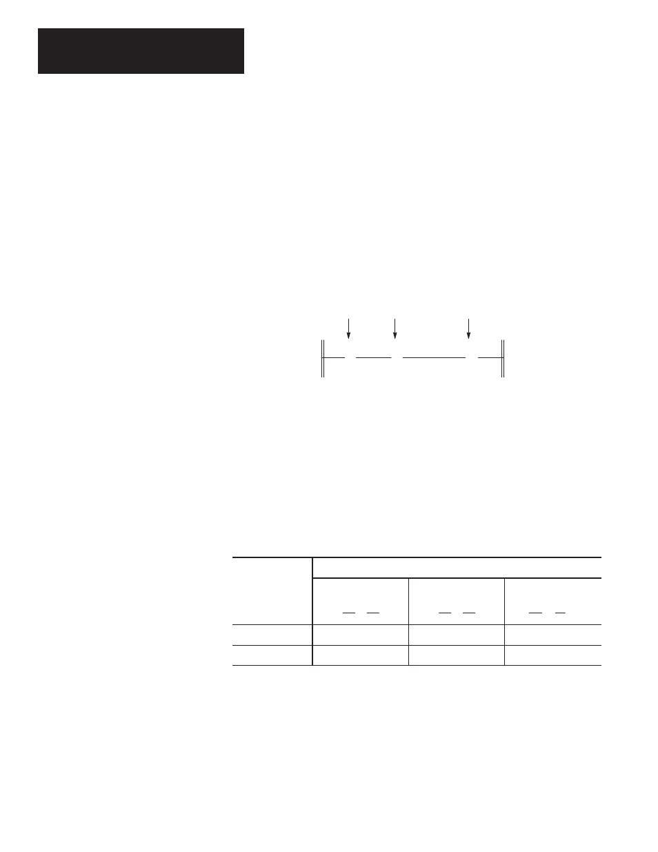
The figure below shows a simple 1–rung ladder program. The rung includes
two input instructions and an output instruction. Note, in the example below
each instruction has a name (Examine if Closed), a mnemonic (XIC), and an
address (I:1/0).
A simple rung, using bit instructions.
XIC
( )
O:3.0
0
] [
I:1.0
0
]/[
I:1.0
1
XIO
OTE
Input Instructions
Output Instruction
XIC = Examine if Closed
XIO = Examine if Open
Address I:1/0
Address I:1/1
Address O:3/0
OTE = Output Energize
True/False Status
The data file bits that these instructions are addressed to will be either a logic
0 (OFF) or a logic 1 (ON). This determines whether the instruction is
regarded as “true” or “false”:
The status of the instruction is
If the data file
bit is
XIC
Examine if Closed
] [
XIO
Examine if Open
]/[
OTE
Output Energize
( )
Logic 0
False
True
False
Logic 1
True
False
True
Ladder Logic Concepts