User-supplied power connection, Led indicators, Battery compartment – Rockwell Automation 1747-PSD Program Storage Device Installation Instructions User Manual
Page 5: Selector switch and pushbutton, 1747-psd features
Program Storage Device 5
Publication 1747-IN001C-EN-P - May 2006
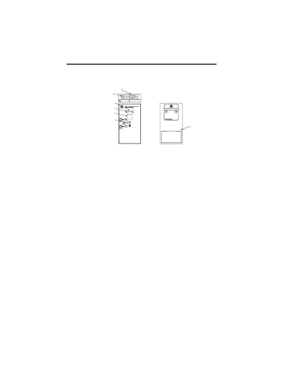
1747-PSD Features
Selector Switch and Pushbutton
The four-position selector switch selects the type of operation performed by the
program storage device. Program Transfer mode functions are labeled on the
program storage device.
The pushbutton executes the selected function. Memory Module mode, Clear
Memory mode, Program Transfer mode, and Secondary Industrial Programming
Station functions are available using the pushbutton in conjunction with the switch.
Battery Compartment
The battery compartment in the back of the program storage device holds two AAA,
1.5V dc standard or alkaline batteries. Batteries are not included with the program
storage device.
The program storage device is Class I, Division 2, Groups A, B, C, and D certified
only when used with batteries.
LED Indicators
The program storage device has a red and a green LED indicator.
User-supplied Power Connection
The program storage device accepts 7...30V dc user-supplied power from a Class 2
power supply adapter.
Error
Linking
Complete - OK
Executing
EXECUTE
FROM PLC
MODE CHANGE
TO PLC
OFF/NEXT CMD
RUN
PROG
Program Storage Device
For use with the PLC communication protocol of
DF1 Full Duplex only
1747-PSD
DO NOT DISCONNECT CONNECTORS
OR OPERATE SWITCHES
UNLESS AREA IS NON-HAZARDOUS
DANGER
EXPLOSION
HAZARD
7-30 VDC
250mA max
C
US
R
LISTED IND. CONT. EQ.
FOR HAZ. LOC. A196
OPERATING TEMPERATURE
CODE T3C
CAT.
SER.
FRN.
1747-PSD
C
3
CLASS
I
, GROUPS A, B, C, AND D, DIV. 2
MADE IN U.S.A.
For Class
I
, Division 2 applications use batteries
only. See Installation Instructions.
N223
Power Supply
Connector
RS-232 Port
Green LED Indicator
Red LED Indicator
Push Button
Battery
Compartment
Front View
Back View
Selector Switch