Bit/word definitions – Rockwell Automation 1794-VHSC 1794 FLEX I/O Very High Speed Counter Module User Manual User Manual
Page 45
Rockwell Automation Publication 1794-UM010D-EN-E - July 2013
37
Communicate With Your Module
Bit/Word Definitions
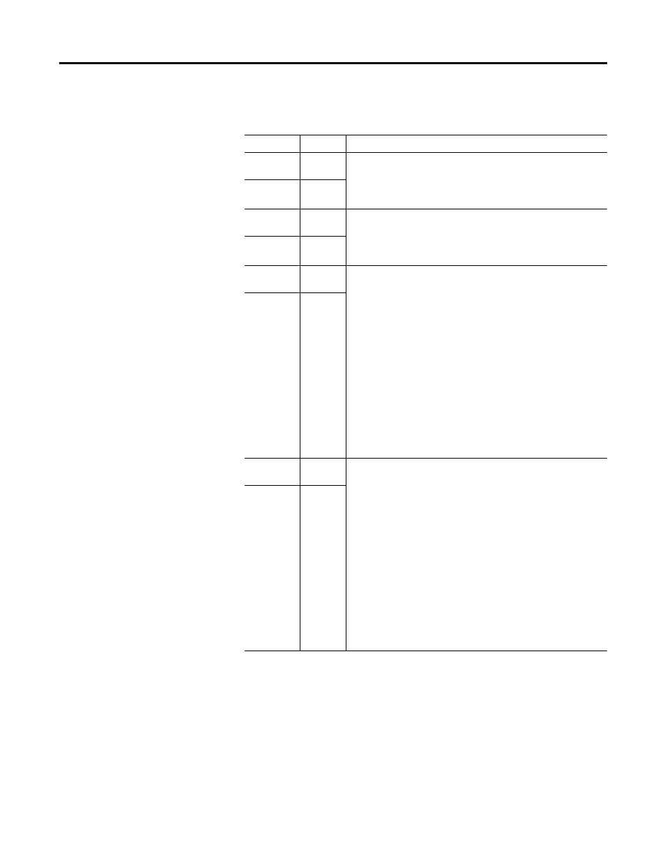
Input Word
Bit
Definition
Word 0
00…15
(00…17)
Channel 0 current count – The current count consists of 2 words (32
bits) representing the current count of the 24-bit counter (in encoder, X2
encoder, X4 encoder, PWM) or the frequency (in periodrate,
continuousrate, rate measurement.). The range of values is
(0 < value < 16,777,215).
Word 1
00…15
(00…17)
Word 2
00…15
(00…17)
Channel 1 current count – The current count consists of 2 words (32
bits) representing the current count of the 24-bit counter (in encoder, X2
encoder, X4 encoder, PWM) or the frequency (in period/rate,
continuous/rate, rate measurement.). The range of values is
(0 < value < 16,777,215).
Word 3
00…15
(00…17)
Word 4
00…15
(00…17)
Channel 0 stored/accumulated count – These are 32-bit long word
values representing the stored count of the counter at the time of some
specified event.
These words are not updated in counter modes (counter, X1 encoder, X2
encoder, X4 encoder) without store modes selected. With store modes
selected, it is the counter value at the time of the specified Z input
event.
In PWM configuration, it is the counter value at the end of the period
specified by the product of the time base times gate interval.
In period/rate and continuous/rate, it is the total accumulation of
unscaled Z pulses (if scaling is set to 128, the accumulator will increase
by 128 counts). The maximum frequency that accumulation can follow is
(200Hz X Scaler value).
In rate measurement, it is the total number of pulses seen at the A input
accumulated over each period as specified by the product of time base
times gate interval. The range of values occupy the entire 32-bit size
from 0 < value < 4,294,967,295. These words are not cleared by
changing the configuration.
Word 5
00…15
(00…17)
Word 6
00…15
(00…17)
Channel 1 stored/accumulated count – These are 32-bit long word
values representing the stored count of the counter at the time of some
specified event.
These words are not updated in counter modes (counter, X1 encoder, X2
encoder, X4 encoder) without store modes selected.With store modes
selected, it is the counter value at the time of the specified Z input
event.
In PWM configuration, it is the counter value at the end of the period
specified by the product of the time base times gate interval.
In period/rate and continuous/rate, it is the total accumulation of
unscaled Z pulses (if scaling is set to 128, the accumulator will increase
by 128 counts). The maximum frequency that accumulation can follow is
(200Hz X Scaler value).
In rate measurement, it is the total number of pulses seen at the A input
accumulated over each period as specified by the product of time base
times gate interval. The range of values occupy the entire 32-bit size
from 0 < value < 4,294,967,295. These words are not cleared by
changing the configuration.
Word 7
00…15
(00…17)