I/o structure, Adapter input status word – Rockwell Automation 1794-VHSC 1794 FLEX I/O Very High Speed Counter Module User Manual User Manual
Page 39
Rockwell Automation Publication 1794-UM010D-EN-E - July 2013
31
Communicate With Your Module
If the configuration is considered acceptable, the counter application specific
integrated circuit (ASIC) is disabled — counting is suspended and outputs are
shut off — while the ASIC is loaded with the new operational parameters.
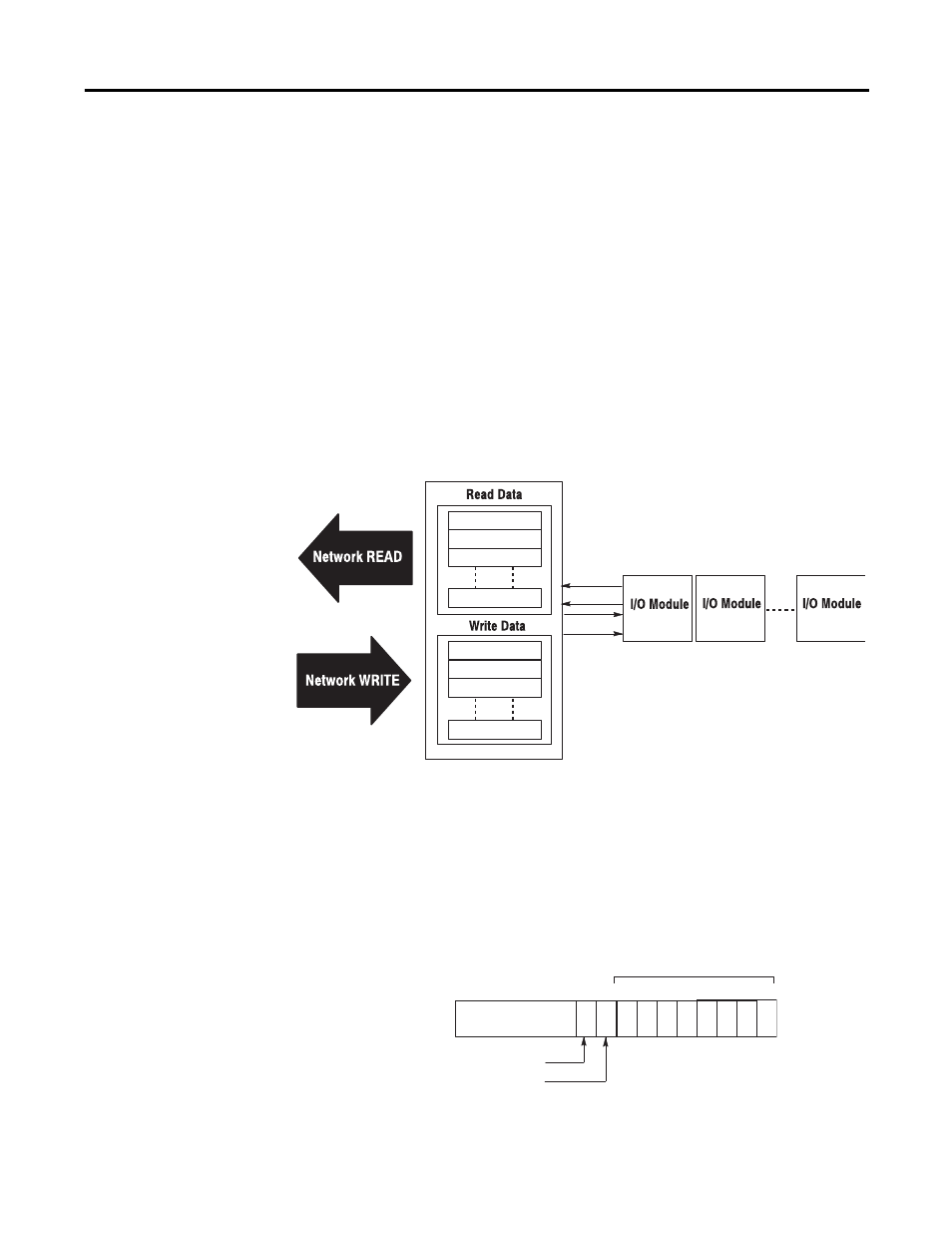
I/O Structure
Output data is received by the adapter in the order of the installed I/O modules.
The Output data for Slot 0 is received first, followed by the Output data for Slot
1, and so on up to slot 7.
The first word of input data sent by the adapter is the Adapter Status Word. This
is followed by the input data from each slot, in the order of the installed I/O
modules. The Input data from Slot 0 is first after the status word, followed by
Input data from Slot 2, and so on up to slot 7.
Adapter Input Status Word
The input status word consists of:
• I/O module fault bits — 1 status bit for each slot
• node address changed — 1 bit
• I/O status — 1 bit
Adapter Status
Read
Write
Slot 0 Input Data
Slot 1 Input Data
Slot 7 Input Data
Adapter Status
Slot 0 Output Data
Slot 1 Output Data
Slot 7 Output Data
EtherNet/IP adapter
Slot 0
Slot 1
Slot 7
45901
I/O Module Fault Bits
Not used
Node Address Changed Bit
Bit:
15
0
14
13
12
11
10
9
8
7
6
5
4
3
2
1
Slot 0
Slot 1
Slot 2
Slot 3
Slot 4
Slot 5
Slot 6
Slot 7
Node Address Changed Bit
Created by controller
{
45902