Sample period, Connection to counter inputs, Pulse width modulation – Rockwell Automation 1794-VHSC 1794 FLEX I/O Very High Speed Counter Module User Manual User Manual
Page 20: Sample period connection to counter inputs, Operation of the rate measurement
12
Rockwell Automation Publication 1794-UM010D-EN-E - July 2013
Overview of the Very High Speed Counter Module
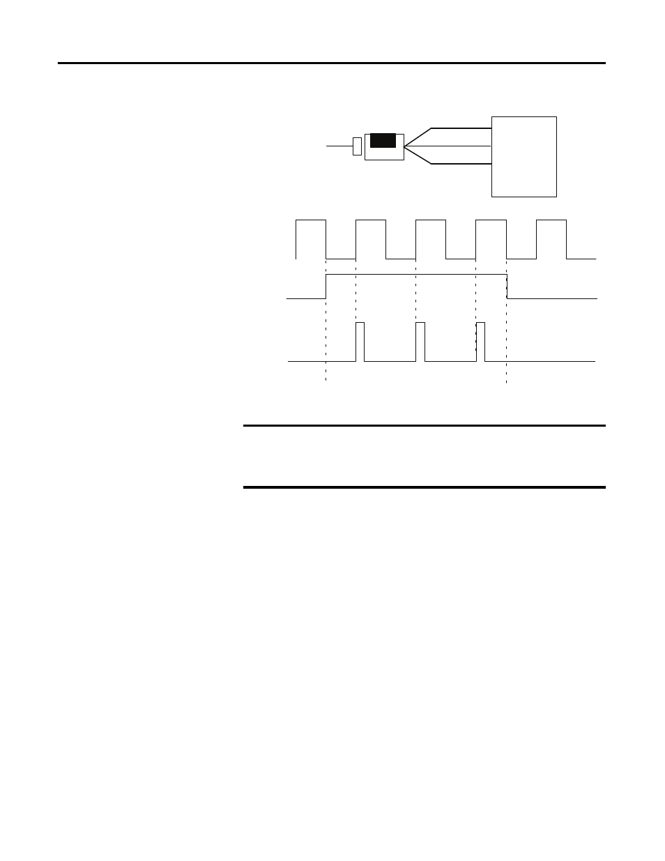
Operation of the Rate Measurement Mode
Sample Period
You can set the sample period used in the frequency calculation in the rate
measurement mode. Allowable values are 10 ms to 3 s in 10 ms increments. The
default value is 1 s.
Connection to Counter Inputs
The only user connections used in the rate measurement mode are to phase A of
the module. The Z (gate/reset) and channel B terminals are not used in
this mode.
Pulse Width Modulation
The module can generate a pulse width modulation signal that may be tied to any
output. By specifying a period (configuration word 2) and gate interval
(configuration word 2 or 3) together with the PWM configuration word 2 or 3, a
counter and its first ON/OFF window comparator is assigned and the signal
generated. The actual duty cycle is specified by output words 2 and 3.
A Input
B (not used)
Input A
Input B
Z (not used)
Encoder/Pulse generator
1794-VHSC
Input Z
(Gate/Reset)
Time base
1
2
3
A Input (pulse)
Internal sampling gate
Accumulated count
Frequency calculated,
outputs updated here
If sample period is 50 ms, and count = 3, then frequency = 3/50 ms = 60 Hz
45895
EXAMPLE
In , three counts have been accumulated during the user-selected time
period. If you had selected 50 ms as the sample period, the frequency
returned to the programmable controller processor would be:
Frequency = Counts/Sample period = 3 counts/50 ms = 60 Hz