Rate measurement mode – Rockwell Automation 1794-VHSC 1794 FLEX I/O Very High Speed Counter Module User Manual User Manual
Page 19
Rockwell Automation Publication 1794-UM010D-EN-E - July 2013
11
Overview of the Very High Speed Counter Module
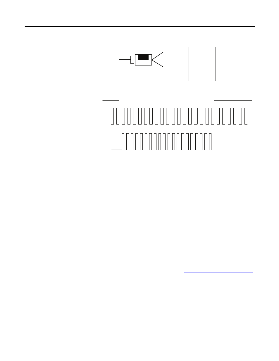
Period/Rate and Continuous/Rate Output Operation with Scaler of 1
Rate Measurement Mode
Use the rate measurement mode to count incoming pulses for a user-specified
time interval. At the end of the interval, the module returns a value representing
the sampled number of pulses and a value indicating the incoming frequency.
When the count and frequency are updated, any associated outputs are checked
against their associated presets.
The value representing the total number of pulses is returned in input file words 4
(LSW) and 5 (MSW) for channel 0 and 6 (LSW) and 7 (MSW) for channel 1,
and the value indicating the incoming frequency is returned in words 0 (LSW)
and 1 (MSW) and 2 (LSW) and 3 (MSW). The total count equals the running
sum of the number of pulses received during the sample period. The operation of
rate measurement mode is shown in Figure
Operation of the Rate Measurement
Incoming pulse train at Z
(gate/reset terminal)
5 MHz internal clock
A (not used)
B (not used)
Input A
Input B
Z
Encoder/Pulse generator
1794-VHSC
Input Z
(Gate/Reset)
scaler
5 MHz clock
1
Accumulated count
Outputs updated continuously
Frequency
updated here
10
20
Assumes symmetrical pulse, 50% duty cycle, so period = sample time on X 2 (on and off)
Frequency = 1/period
If count = 25, scaler = 1, and clock period = (1/5 MHz)
Frequency = 1 / [(25/1) X (1/5 MHz) X 2] = 100 KHz
45894