Encoder mode – Rockwell Automation 1794-VHSC 1794 FLEX I/O Very High Speed Counter Module User Manual User Manual
Page 12
4
Rockwell Automation Publication 1794-UM010D-EN-E - July 2013
Overview of the Very High Speed Counter Module
Block Diagram of Counter Mode
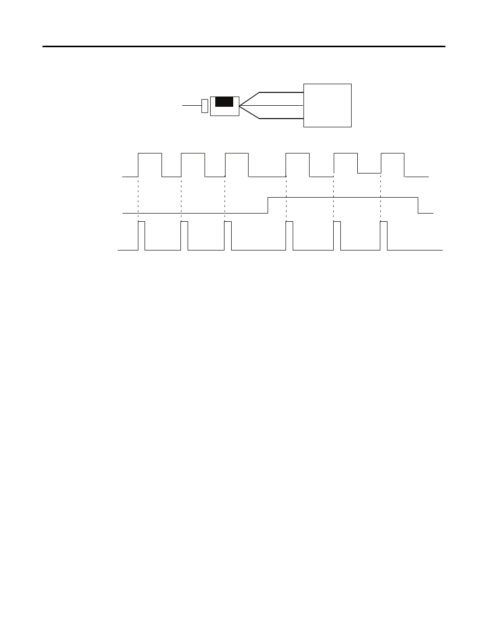
Encoder Mode
The encoder mode allows the module to read incoming pulses and return them to
the programmable controller processor as a binary number (0-16,777,215).
In this mode, the module will accept two phase quadrature feedback. The module
senses the relationship between the 2 phases and counts up or down accordingly.
Encoder X1 mode
– quadrature input signals count on the leading edge or the
trailing edge of channel A for a bidirectional count. The phase relationship
between Channel A and Channel B determines direction — channel A leading,
and channel B floating, the count direction is up; Channel A lagging, and
Channel B high, the count direction is down.
Encoder X2 mode
– quadrature input signals count on the leading edge and the
trailing edge of channel A for a bidirectional count. Channel B determines
direction —B low (floating), the count direction is up; B high, the count
direction is down.
Encoder X4 mode
– quadrature input signals count on the leading edge and the
trailing edge of channel A and channel B for a bidirectional count. Channel B
determines direction — B low (floating), the count direction is up; B high, the
count direction is down.
A
B
0
1
2
3
2
1
0
Input A
Input B
Z (Store count)
Single phase pulse generator
1794-VHSC
Input Z
(Gate/Reset)
Count down
A input
B input
Count
Count up
+
-
Outputs updated continuously
45891