Counter mode – Rockwell Automation 1794-VHSC 1794 FLEX I/O Very High Speed Counter Module User Manual User Manual
Page 11
Rockwell Automation Publication 1794-UM010D-EN-E - July 2013
3
Overview of the Very High Speed Counter Module
Use the encoder modes if you need the module to read incoming quadrature
pulses and return them to the programmable controller as a binary number
(0…16,777,215). In these modes, the module accepts two-phase quadrature
feedback and counts up or down depending upon the condition of the phase B
input for each counter.
The operation of the module in the encoder/counter modes is as follows:
•
counter mode – channel B is direction control (up or down). Channel A
input is used for pulse. The count is bidirectional with the direction
determined by channel B.
•
encoder X1 – This is a bidirectional count mode; counting up or down,
using quadrature input signals.
•
encoder X2 – This is a bidirectional count mode, using quadrature input
signals, with 2 times the resolution of X1.
•
encoder X4 – This is a bidirectional count mode, using quadrature input
signals, with 4 times the resolution of X1.
Each of the counters in encoder/counter mode has values associated with it.
These are:
•
preset value
•
rollover value
Counter Mode
The counter mode allows the module to read incoming pulses and return them to
the programmable controller processor as a binary number (0…16,777,215).
In the counter mode, direction (up counting or down counting) is determined by
the phase B input, which can be a random signal. If Phase B is high, the counter
will count down. If phase B is low or floating, (that is, not connected), the
counter counts up.
The module reads incoming pulses from a maximum of 2 encoders (single-ended
or differential), counters, pulse generators, mechanical limit switches, and so
forth and returns a count to the programmable controller processor in a binary
number (0-16,777,215).
The counter mode accepts only one phase feedback. This relationship is shown in
Figure
Block Diagram of Counter Mode on page 4
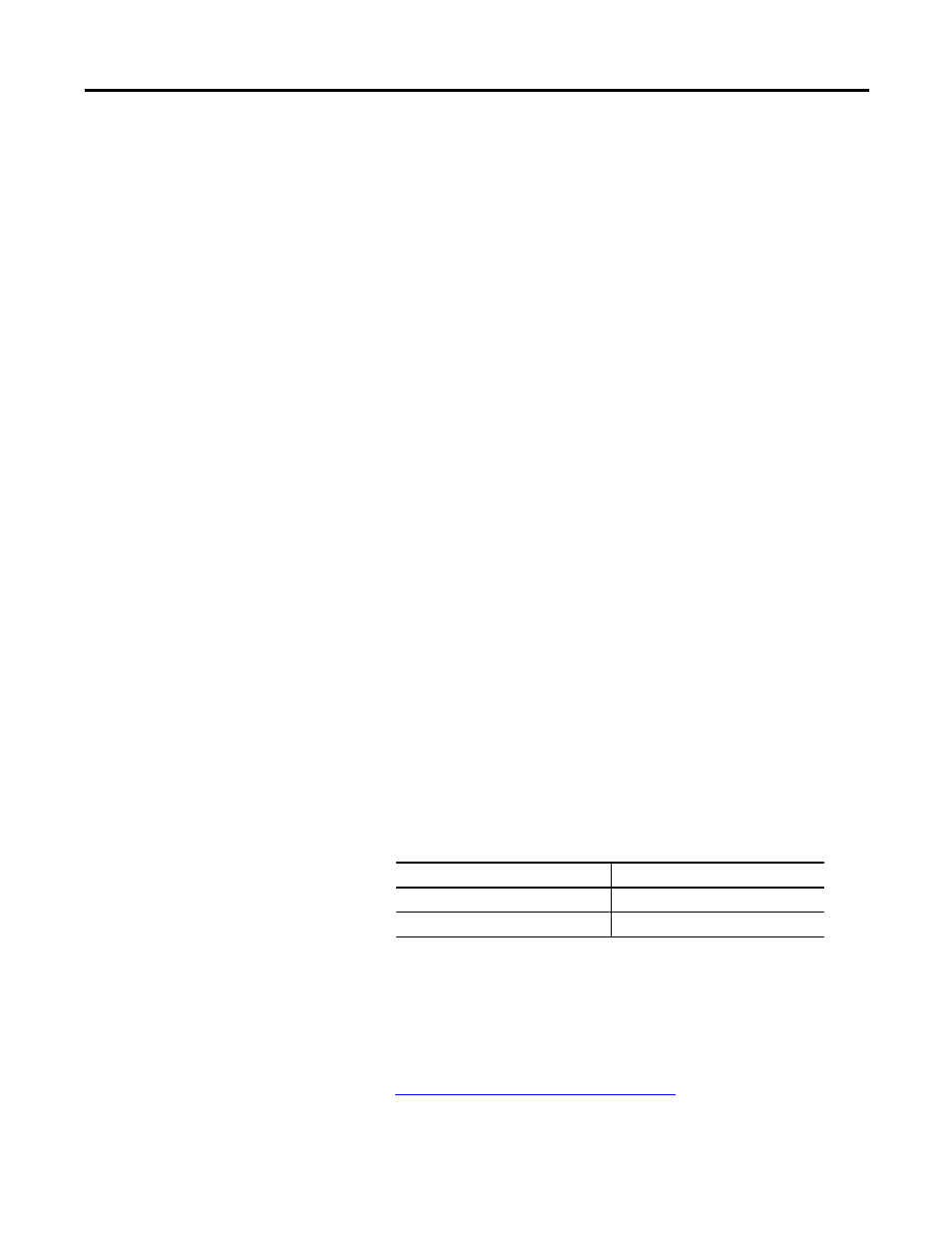
Counter Mode Direction
Phase B Input
Count direction
High
Down
Low or floating (not included)
Up