Operation of scaler, Connection to counter inputs, Continuous/rate mode – Rockwell Automation 1794-VHSC 1794 FLEX I/O Very High Speed Counter Module User Manual User Manual
Page 18: Operation of scaler connection to counter inputs
10
Rockwell Automation Publication 1794-UM010D-EN-E - July 2013
Overview of the Very High Speed Counter Module
Operation of Scaler
In period/rate mode, the scaler lets the incoming pulse train at the Z (gate/reset)
terminal be divided by a user defined number. Acceptable values for the scaler are
1, 2, 4, 8, 16, 32, 64 and 128. There is one scaler value for each counter.
Connection to Counter Inputs
The only input to the module in the period/rate mode is made to the Z (gate/
reset) terminal. The counter inputs (channel A and B) are not used in the period/
rate mode.
Continuous/Rate Mode
The continuous/rate mode is similar to the period/rate mode previously
described except the outputs in this mode are dynamic outputs. Use this mode to
determine the frequency of input pulses by counting the number of internal
5 MHz clock pulses over a user-specified number of input signal pulses. Each
output is turned on as soon as the turn-on count is reached, and turned off as
soon as the turn-off count is reached. As the internal 5 MHz clock is counted, the
outputs dynamically track the 5 MHz count. This allows you to turn an output
on a certain number of 5 MHz counts after the gate/reset pin goes active, and
turn it off a certain number of 5 MHz counts later.
1794-VHSC module counts the total number of pulses occurring at the Z (gate/
reset) terminal. This function is frequency-limited to 200 Hz X the scaler value.
This total count is returned in input file words 4 (LSW) and 5 (MSW) for
channel 0 and 6 (LSW) and 7 (MSW) for channel 1. You can reset this count by
setting the VR bit.
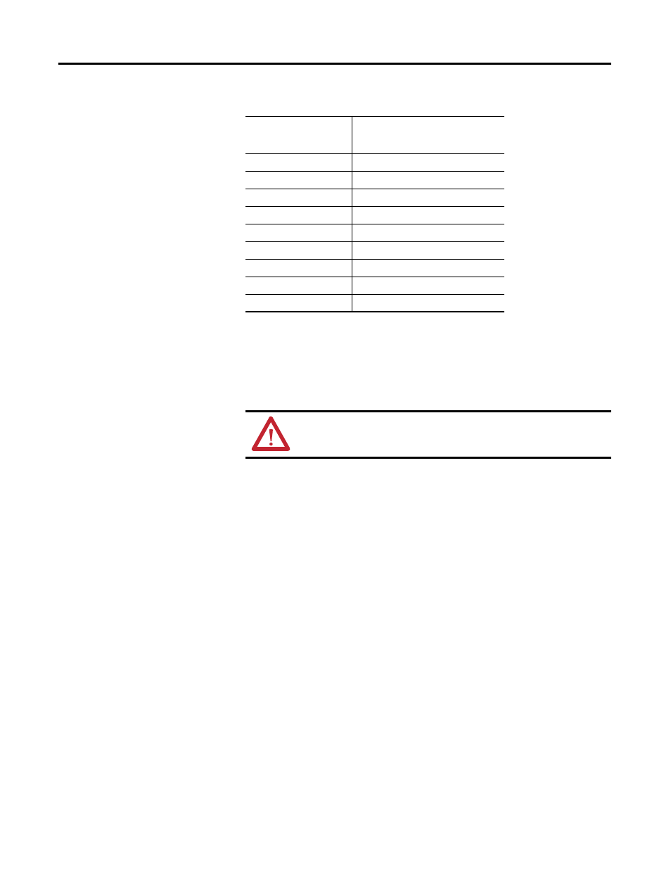
200
12.5K
500
5K
1 KHz
2.5K
2 KHz
1.25k
5 KHz
500
10 KHz
250
20 KHz
125
50 KHz
50
100 KHz
25
ATTENTION: Sample period times scaler must be less than 6.71 s in
order to avoid a zero frequency detect indication.
Relationship Between Sampled Pulses and Input Frequency
Input Frequency at Z
(Gate/Reset)
Terminal in Hz
Sampled Pulses for 1/2 Cycle of Z
(Gate/Reset) Pulse