Plc-3 family processors – Rockwell Automation 1771-IXE/D Thermocouple/Millivolt Input Module User Manual User Manual
Page 60
Programming Examples
B–2
Publication 1771-6.5.130 Ć May 1999
Use the above procedure to enter the required words of the write
block transfer instruction. Be aware that the block length will depend
on the number of channels selected and whether alarming or user
calibration are implemented. For example, the block may contain
only 1 word if no alarming or user calibration are implemented, but
may contain 27 words if using 8 inputs with alarming and user
calibration. The PLC–2 family write block transfer data file should
look like Figure B.1.
Figure B.1
Write Block Transfer Data Transfer for a PLC-2 Family
Processor
00000000 00000000
00000000 00000000
00000000 00000000
00000000 00000000
00000000 00000000
00000000 00000000
00000000 00000000
00000000 00000000
00000000 00000000
00000000 00000000
00000000 00000000
00000000 00000000
00000000 00000000
00000000 00000000
00000000 00000000
00000000 00000000
001
002
003
004
005
006
007
008
POSITION
FILE DATA
DATA ADDR: 030
BINARY DATA MONITOR
BLOCK LENGTH: 27
BLOCK XFER WRITE
MODULE ADDR: 110
FILE: 400-432
Following is a sample procedure for entering data in the
configuration words of the write block transfer instruction when
using a PLC–3 processor. For a complete sample program, refer to
Figure Figure 3.2.
To enter data in the configuration words, follow these steps:
Example:
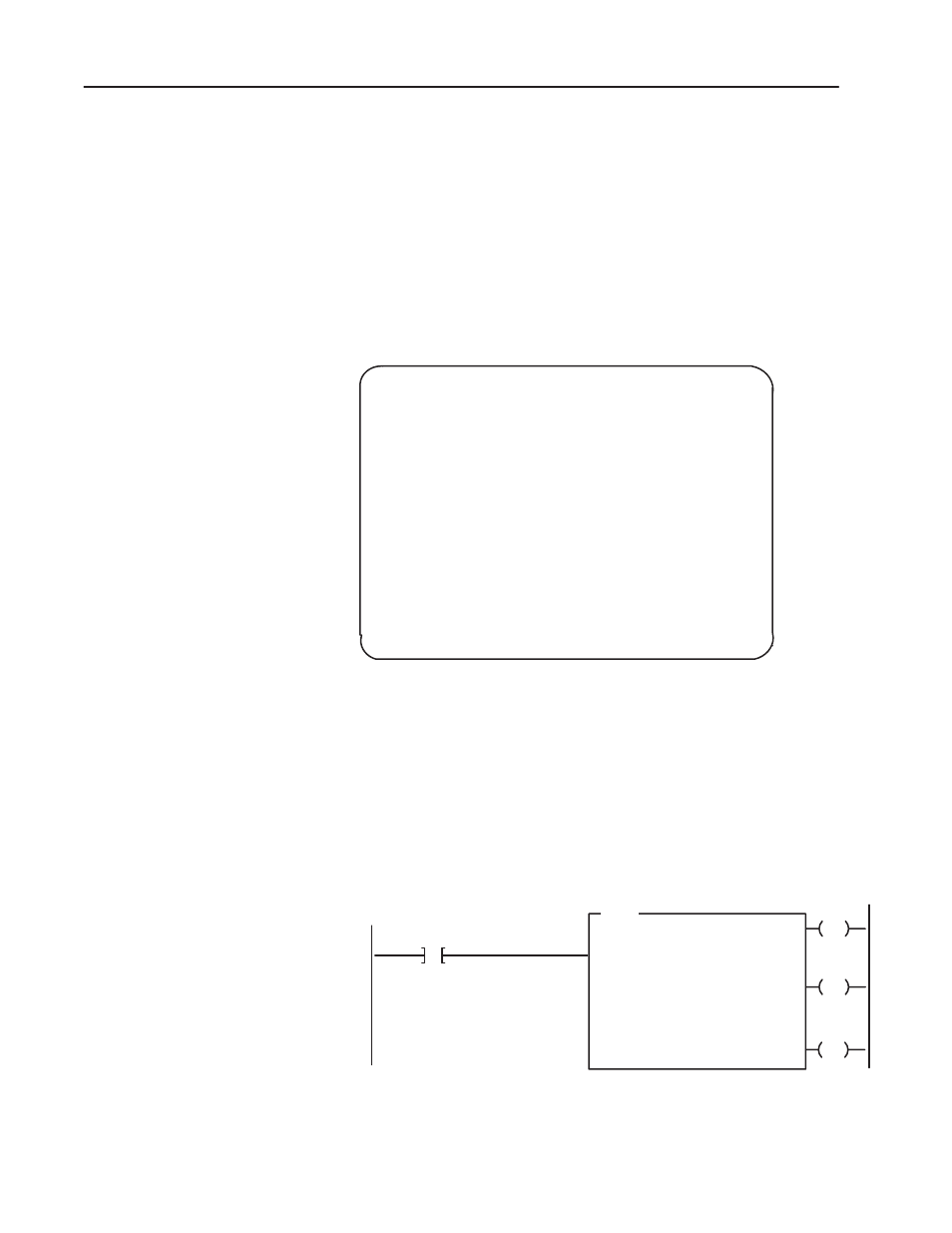
Enter the following rung for a write block transfer:
EN
BTW
RACK:
GROUP:
MODULE
DATA:
001
1
1 = HIGH
F0003:0000
DN
ER
LENGTH:
27
CNTL:
FB004:0000
BLOCK XFER WRITE
CNTL
CNTL
CNTL
13
15
12
Power Up Bit
F0003:0000 is the address of the write block transfer data file. You
want to enter/examine word 1.
PLC-3 Family Processors