Bit/word descriptions – Rockwell Automation 1771-IXE/D Thermocouple/Millivolt Input Module User Manual User Manual
Page 34
4–6
Module Configuration
Publication 1771Ć6.5.130 Ć May 1999
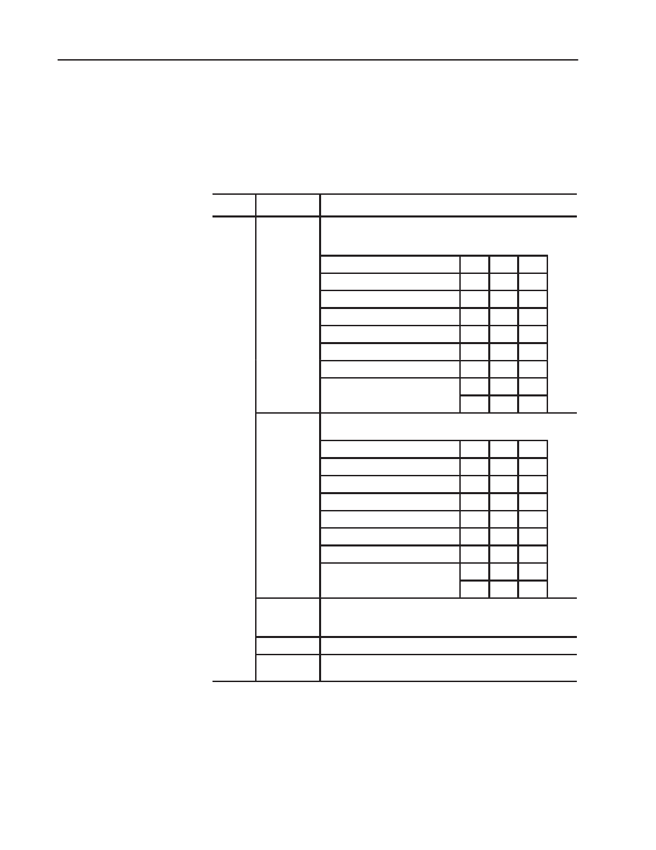
Bit/word descriptions of BTW file words 1 thru 3 (configuration), 4
thru 19 (channel alarm values), and 20 thru 27 (calibration values)
are presented in Table 4.E. Enter data into the BTW instruction after
entering the instruction into your ladder diagram program.
Table 4.E
Bit/Word Definitions for Thermocouple/Millivolt Input
Module
Word
Bits
Description
Word 1
bits 00-02
Input type codes for inputs 1 thru 8 (or 1 thru 4 if bit 06 is set to 1).
Tells the module what type of input device you connected to the
module.
Type
02
01
00
Millivolt input
0
0
0
"E" thermocouple
0
0
1
"J" thermocouple
0
1
0
"K" thermocouple
0
1
1
"T" thermocouple
1
0
0
"R" thermocouple
1
0
1
"S" thermocouple
1
1
0
1
1
1
bits 03-05
Input type codes for inputs 5 thru 8 (bit 06 must be set to 1). Tells the
module what type of input device you connected to inputs 5 thru 8.
Type
05
04
03
Millivolt input
0
0
0
"E" thermocouple
0
0
1
"J" thermocouple
0
1
0
"K" thermocouple
0
1
1
"T" thermocouple
1
0
0
"R" thermocouple
1
0
1
"S" thermocouple
1
1
0
1
1
1
bit 06
When set to 0 bits 00-02 define input type for all channels.
When set to 1 bits 00-02 defines input type for channels 1-4,
and bit 03-05 defines input type for channels 5-8.
bit 07
Not used (set to 0)
bit 10
Temperature scale bit, when set, reports temperature in
o
F; when
reset, in
o
C. The module ignores this bit for millivolt inputs.
Bit/Word Descriptions