Plcć5 programming example – Rockwell Automation 1771-IXE/D Thermocouple/Millivolt Input Module User Manual User Manual
Page 27
3–5
Module Programming
Publication 1771Ć6.5.130 Ć May 1999
Rungs 1 and 2 – Rungs 1 and 2 are the block transfer read and write
instructions. The BTR enable bit in rung 1, being false, initiates the
first read block transfer. After the first read block transfer, the
module performs a block transfer write and then does continuous
block transfer reads until the pushbutton is used to request another
block transfer write. After this single block transfer write is
performed, the module returns to continuous block transfer reads
automatically.
The PLC–5 program is very similar to the PLC–3 program with the
following exceptions:
•
You must use enable bits instead of done bits as the conditions on
each rung.
•
A separate control file must be selected for each of the BT
instructions. Refer to Appendix B.
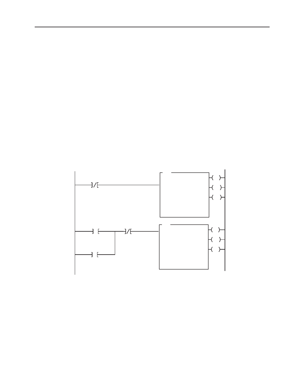
Figure 3.3
PLC-5 Family Sample Program Structure
EN
BTR
BLOCK XFER READ
RACK:
GROUP:
MODULE:
CONTROL:
X
X
X
XXX:XX
DN
DATA FILE:
LENGTH:
CONTINUOUS:
XXX:XX
XX
N
ER
EN
BTW
BLOCK XFER WRITE
RACK:
GROUP:
MODULE:
CONTROL:
X
X
X
XXX:XX
DN
DATA FILE:
LENGTH:
CONTINUOUS:
XXX:XX
XX
N
ER
BTR Enable
Power-up Bit
Pushbutton
BTW Enable
1
2
Program Action
Rungs 1 and 2 – At power–up, the program enables a block transfer
read and examines the power–up bit in the BTR file (rung 1). Then,
it initiates one block transfer write to configure the module (rung 2).
Thereafter, the program continuously reads data from the module
(rung 1).
A subsequent BTW operation is enabled by a pushbutton switch
(rung 2). Changing processor mode will not initiate a block transfer
write unless the first pass bit is added to the BTW input conditions.
PLCĆ5 Programming
Example