Programming chapter 3 – Rockwell Automation 1772-AF1,D17726.5.1 User Manual MINI-PLC-2/15 User Manual
Page 45
Programming
Chapter 3
3Ć37
3.
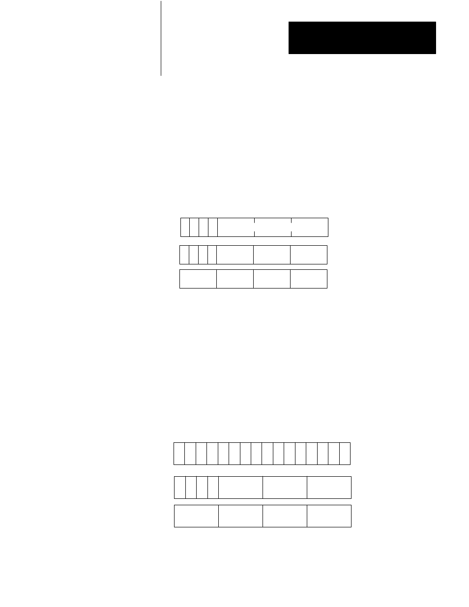
Enter a data address and a result address.
If we choose a data address of 200 and a result address of 300, the data table
format is as shown in Figure 3.35. Bits 0 through 13 of word 200 are reserved
for the operand (the 12-bit binary number we want to convert to BCD). The
result address, 300, contains the most significant three digits of the resulting
BCD number. The least significant three digits reside in the next higher
address, 301. The first two digits of the BCD number are always zero and the
third digit can not exceed four.
Figure 3.35
AF1 Binary to BCD Conversion Function Format After Address Entry
17 16 15 14 13 12 11 10 7 6 5 4 3 2 1 0
S
Digit 1 (MSD)
(Always = 0)
Digit 3
Bit No.
Data Address
Digit 5
S
Result Address
Result
D
E
E = Enable Bit (1 = Function in Progress)
S = Sign Bit (1= Negative)
D = Done Bit (1 = Function Complete)
MSD = Most Significant Digit
LSD = Least Significant Digit
11497
Operand
Digit 4
Digit 6
(LSD)
Digit 2
(Always = 0)
12 Bit Binary Number
200
300
301
4.
Enter the operand.
You can enter the operand from the keyboard of your industrial terminal or
through ladder diagram functions. If we choose to set bits 0 through 13 in word
200, that is, insert the largest possible binary number in 12 bits, we obtain 4095
for the corresponding BCD number (Figure 3.36). The ones in bits 0 through
13 or word 200 indicate that each bit is set.
Figure 3.36
AF1 Binary to BCD Conversion Function Format After Execution
17 16 15 14 13 12 11 10 7 6 5 4 3 2 1 0
S
Bit No.
Data Address
S
Result Address
Result
D
E
E = Enable Bit (1 = Function in Progress)
S = Sign Bit (1= Negative)
D = Done Bit (1 = Function Complete)
11498
Operand
200
300
301
(0) (0) (1)
0
0
4
0
9
5
1 1 1 1 1 1 1 1 1 1 1 1