Programming chapter 3 – Rockwell Automation 1772-AF1,D17726.5.1 User Manual MINI-PLC-2/15 User Manual
Page 15
Programming
Chapter 3
3Ć7
2. Enter 01, the function number for AF1 addition.
This entry identifies that the function entered is to perform an AF1 addition and
that the processor use the data table format shown in Figure 3.2 when executed.
Operands 1 and 2 represent the two 6-digit numbers you wish to add. The six
digits of operand 1 are represented in BCD by the groups of bits labeled digit 1
through 6. Digit 1 and digit 6 are the most significant and the least significant
digits respectively. This digit labeling system also applies to operand 2 and the
result.
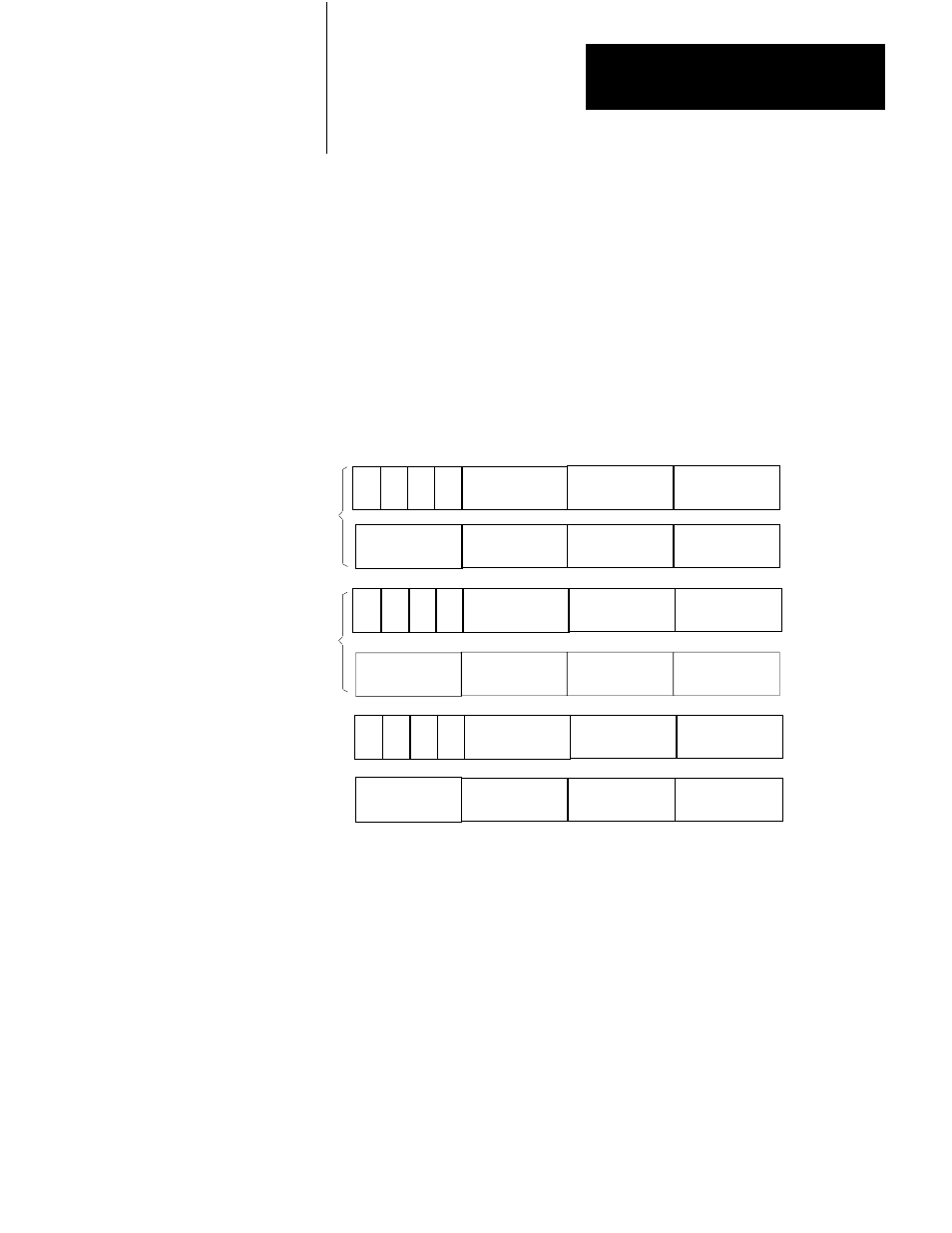
Figure 3.2
General AF1 Addition Function Word and Digit Format
17 16 15 14 13 12 11 10 7 6 5 4 3 2 1 0
S
Digit 1
(MSD)
Digit 2 Digit 3
Bit No.
Digit 4 Digit 5
Digit 6
(LSD)
S
Digit 1
(MSD)
Digit 2 Digit 3
Digit 4 Digit 5
Digit 6
(LSD)
S
Digit 1
(MSD)
Digit 2 Digit 3
E D ER
Digit 4 Digit 5
Digit 6
(LSD)
Operand 1
Operand 2
Result
Data Address
m
m + 1
m + 2
m + 3
Result Address
n
n + 1
E = Enable Bit (1 = Function in Progress)
S = Sign Bit (1 = Negative)
D = Done Bit ( 1= Function Complete)
ER = Error Bit (1 = Overflow)
MSD = Most Significant Digit
LSD = Least Significant Digit
11481
3. Enter a data address and a result address.
If we select a data address of 201 and a result address of 305, the AF1
establishes the data table format shown in Figure 3.3. Be careful not to select
data and result addresses so close together that the addresses of the operands
following the data address overlap your result address. The data address
eventually contains three digits of operand 1. The AF1 reserves the next three
higher addresses for digits 4 through 6 of operand 1 and digits 1 through 6 of
operand 2. The result address contains the most significant three digits of the
result and the next higher address contains the least significant three digits.