Programming chapter 3 – Rockwell Automation 1772-AF1,D17726.5.1 User Manual MINI-PLC-2/15 User Manual
Page 31
Programming
Chapter 3
3Ć23
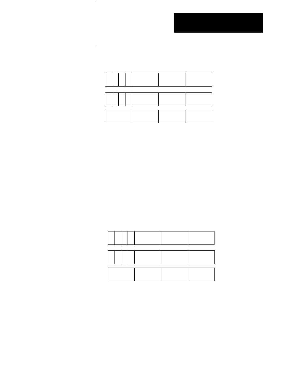
Figure 3.18
General AF1 Square Root Function Word and Digit Format
17 16 15 14 13 12 11 10 7 6 5 4 3 2 1 0
S
Digit 1
(MSD)
Digit 2
Digit 3
Bit No.
Data Address
Operand
m
S
Digit 1 (MSD)
Digit 2
Digit 3
Result Address
Digit 5
Digit 4
D
E
Digit 6
n
n + 1
E = Enable Bit (1 = Function in Progress)
S = Sign Bit (1= Negative)
D = Done Bit (1 = Function Complete)
MSD = Most Significant Digit
LSD = Least Significant Digit
11582
(LSD)
(Always = 0)
(LSD)
(Always = 0)
Result
3.
Enter a data address and a result address.
If we enter a data address of 200 and a result address of 305, the AF1
establishes the data table format shown in Figure 3.19. The data address
eventually contains the three digits of the number whose square root is sought.
The result address (word 305) contains the first three digits (integer part) of the
result. The three decimal digits of the result are stored in the next higher
address, word 306. The implied decimal point is between digits 3 and 4.
Figure 3.19
AF1 Square Root Function Format After Address Entry
17 16 15 14 13 12 11 10 7 6 5 4 3 2 1 0
S
Digit 1
(MSD)
Digit 2
Digit 3
Bit No.
Data Address
Operand
200
S
Digit 1
Digit 2
Digit 3
Result Address
Digit 5
Digit 4
D
E
Digit 6
305
306
E = Enable Bit (1 = Function in Progress)
S = Sign Bit (1= Negative)
D = Done Bit (1 = Function Complete)
MSD = Most Significant Digit
LSD = Least Significant Digit
11583
(LSD)
(Always = 0)
(LSD)
(Always = 0)
Result
(MSD)