Programming chapter 3 – Rockwell Automation 1772-AF1,D17726.5.1 User Manual MINI-PLC-2/15 User Manual
Page 42
Programming
Chapter 3
3Ć34
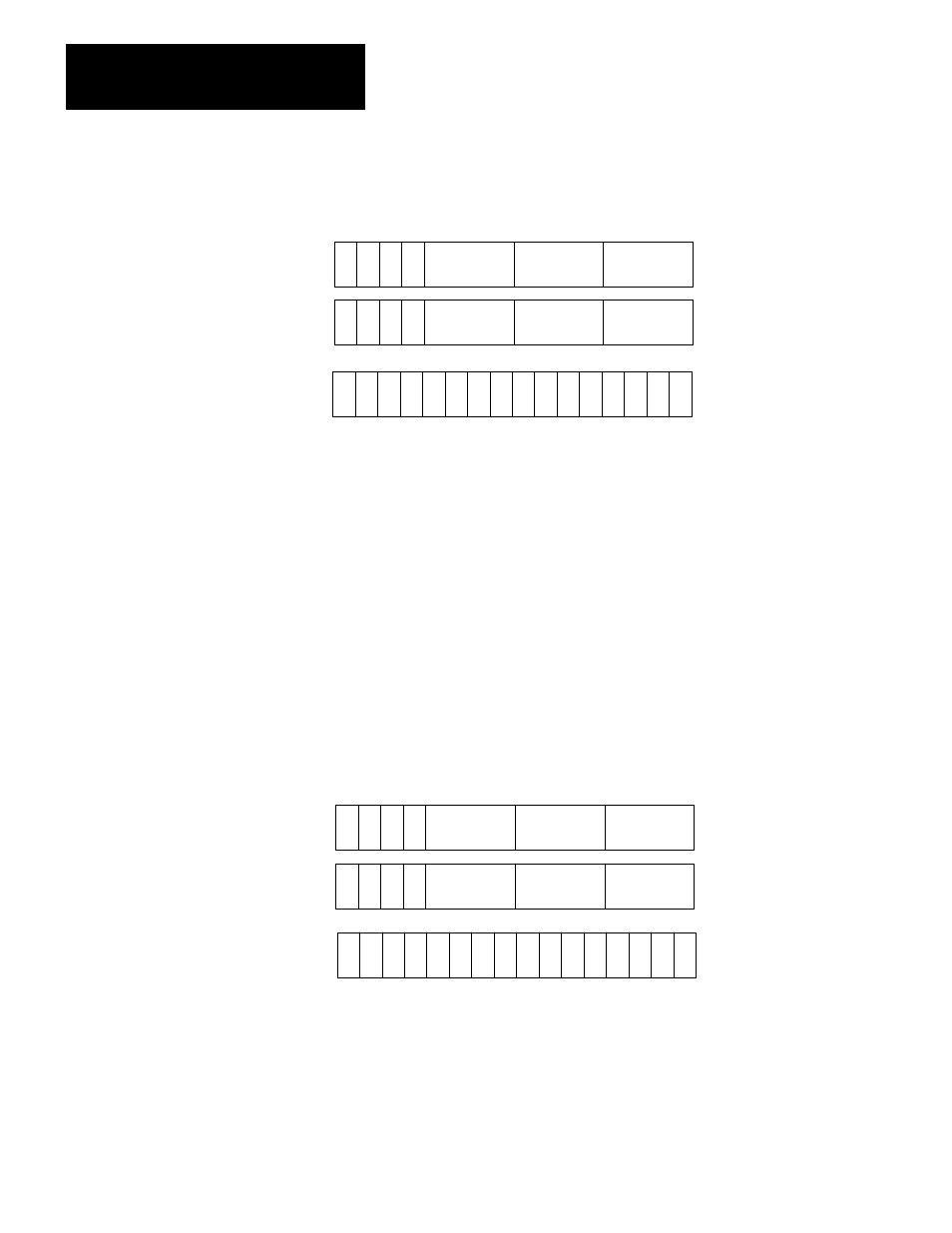
Figure 3.30
General AF1 BCD to Binary Conversion Function Word and Digit Format
17 16 15 14 13 12 11 10 7 6 5 4 3 2 1 0
S
Digit 1 (MSD)
(Always = 0)
Digit 3
Bit No.
Data Address
Digit 5
S
Result Address
Result
D
E
E = Enable Bit (1 = Function in Progress)
S = Sign Bit (1= Negative)
D = Done Bit (1 = Function Complete)
MSD = Most Significant Digit
LSD = Least Significant Digit
11493
ER
ER = Error Bit (1 = BCD Number > 4095 Entered)
m
m + 1
n
Operand
Digit 4
Digit 6
(LSD)
Digit 2
(Always = 0)
(Must be
3
4)
3.
Enter a data address.
If we choose a data address of 200 and a result address of 300, the data table
format is as shown in Figure 3.31. The most significant three digits of the
operand (the BCD number we want to convert to binary) reside in the data
address word 200 and the least significant three digits reside in the next higher
address, 201. The first two digits are always zero and the third digit must not
exceed four. The number, converted to binary format, is stored in bits 0 through
13 in the result address, word 300.
Figure 3.31
AF1 BCD to Binary Conversion Function Format After Address Entry
17 16 15 14 13 12 11 10 7 6 5 4 3 2 1 0
S
Digit 1 (MSD)
(Always = 0)
Digit 3
Bit No.
Data Address
Digit 5
S
Result Address
Result
D
E
E = Enable Bit (1 = Function in Progress)
S = Sign Bit (1= Negative)
D = Done Bit (1 = Function Complete)
MSD = Most Significant Digit
LSD = Least Significant Digit
11494
ER
ER = Error Bit (1 = BCD Number > 4095 Entered)
Operand
Digit 4
Digit 6
(LSD)
Digit 2
(Always = 0)
200
201
300
(Must be
3
4)