Filter selection, Scalar selection – Rockwell Automation 1734-IK/C POINT I/O 5V and 24V Encoder/Counter Module Installation Instructions User Manual
Page 14
14 POINT I/O™ 5V and 24V Encoder/Counter Modules
Publication 1734-IN005G-EN-E - September 2012
The Encoder/Counter Module uses several words to communicate real-time input and
output data as well as non-real time module information, that is, description, revision, and
configuration. This shows the words that you can exchange. You can read (get) or write
(set) data using an Explicit Message.
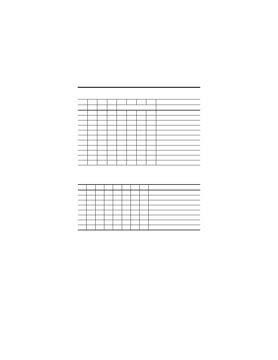
Filter Selection
(1)
07
06
05
04
03
02
01
00
0
ZF
BF
AF
FS
0
0
0
0
No filter
0
0
0
1
50 kHz (10
μ
s + 0
μ
s/-1.6
μ
s)
0
0
1
0
5 kHz (100
μ
s + 0
μ
s/-13.2
μ
s)
0
1
0
0
500 Hz (1 ms + 0
μ
s/-125
μ
s)
1
0
0
0
50 Hz (10 ms + 0 ms/-1.25 ms)
0
A input not filtered
1
A input filtered
0
B input not filtered
1
B input filtered
0
Z input not filtered
1
Z input filtered
(1)
Assumes a 50% duty cycle signal.
Scalar Selection
07
06
05
04
03
02
01
00
Scalar
(1)
0
0
0
0
0
0
0
1
Z – F
min
= 0.149 Hz
0
0
0
0
0
0
1
0
Z/2 – F
min
= 0.298 Hz
0
0
0
0
0
1
0
0
Z/4 – F
min
= 0.596 Hz
0
0
0
0
1
0
0
0
Z/8 – F
min
= 1.192 Hz
0
0
0
1
0
0
0
0
Z/16 – F
min
= 2.384 Hz
0
0
1
0
0
0
0
0
Z/32 – F
min
= 4.768 Hz
0
1
0
0
0
0
0
0
Z/64 – F
min
= 9.537 Hz
1
0
0
0
0
0
0
0
Z/128 – F
min
= 19.073 Hz
(1)
Where F
min
indicates the frequency at which the zero frequency detect is asserted due to counter overflow.