Counter configuration – Rockwell Automation 1734-IK/C POINT I/O 5V and 24V Encoder/Counter Module Installation Instructions User Manual
Page 13
POINT I/O™ 5V and 24V Encoder/Counter Modules 13
Publication 1734-IN005G-EN-E - September 2012
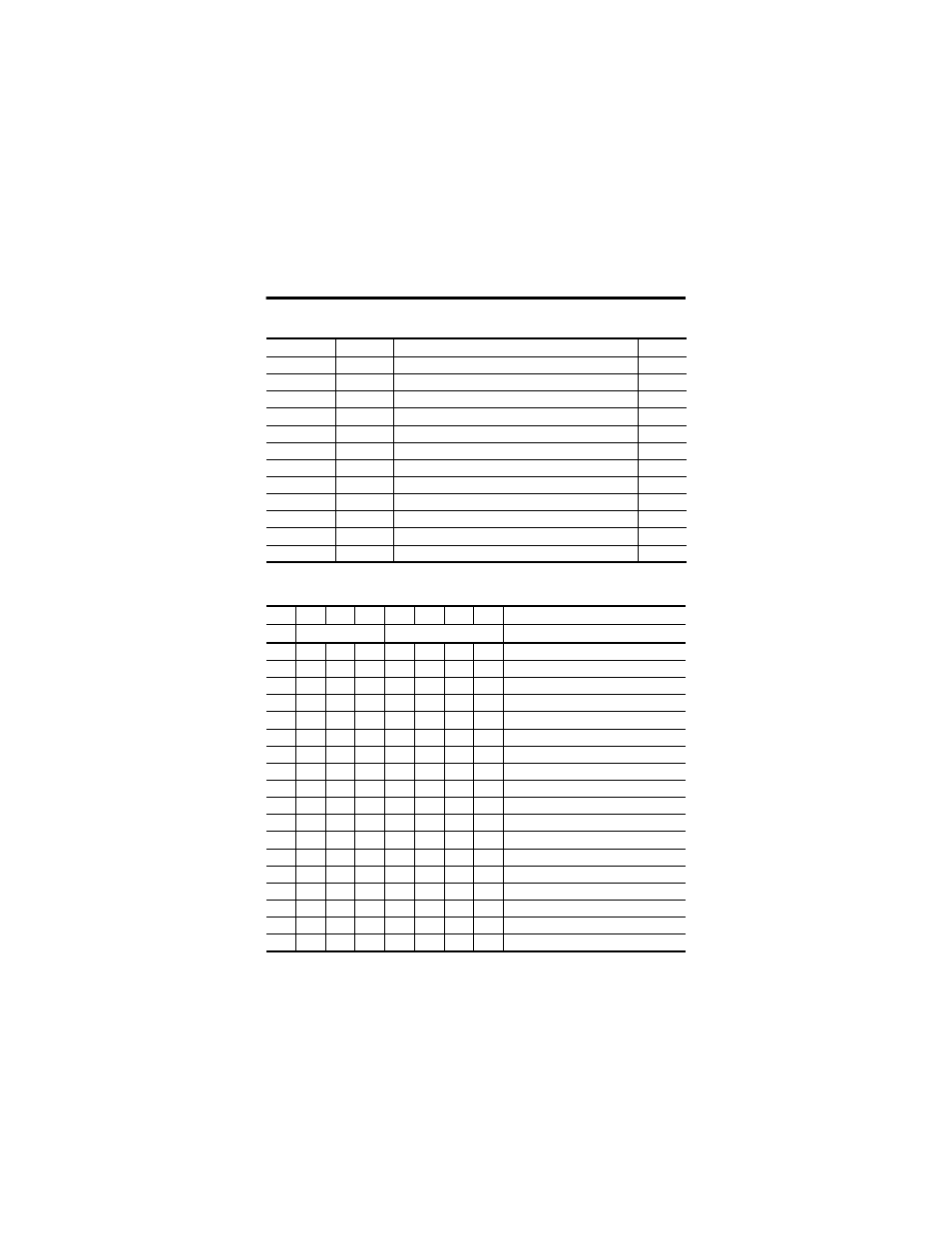
Module Configuration
Parameter
Set/Get
Description
Bytes
1
Set/Get
Counter configuration
1
2
Set/Get
Filter selection
1
3
Set/Get
Decimal position
1
4
Set/Get
Reserved
1
5
Set/Get
Time base value
2
6
Set/Get
Gate interval
1
7
Set/Get
Channel scalar
1
8
Set/Get
Channel rollover value
4
9
Set/Get
Channel preset value
4
10
Set/Get
Counter control safe state
1
11
Set/Get
Requested poll produce assembly
1
12
Set/Get
Requested change of state produce assembly
1
Counter Configuration
07
06
05
04
03
02
01
00
ZI
MD
CF
Counter 0
0
0
0
0
Counter
0
0
0
1
Encoder X1
0
0
1
0
Encoder X2
0
0
1
1
Not used
0
1
0
0
Encoder X4
0
1
0
1
Period/Rate
0
1
1
0
Not used
0
1
1
1
Rate measurement
0
0
0
Store count disabled
0
0
1
Mode 1 – store/continue
0
1
0
Mode 2 – store/wait/resume
0
1
1
Mode 3 – store, reset/wait/start
1
0
0
Mode 4 – store, reset/start
1
0
1
Reserved
1
1
0
Reserved
1
1
1
Reserved
0
Z input – 0 = not inverted
1
Z input – 1 = inverted