Communicate with your module – Rockwell Automation 1734-IK/C POINT I/O 5V and 24V Encoder/Counter Module Installation Instructions User Manual
Page 12
12 POINT I/O™ 5V and 24V Encoder/Counter Modules
Publication 1734-IN005G-EN-E - September 2012
Communicate with Your Module
POINT I/O modules send (consume) and receive (produce) I/O messages. You map these
messages into the processor’s memory.
These modules produce 6 or 10 Bytes of input data (scanner Rx) (status). These modules
consume 1 Byte of I/O data (scanner Tx). Use parameters 11 and 12 to select assembly
101, 102, or 103 for data produced by the modules.
When you send a configuration to the module, check for consistency before applying it.
Monitor the PE bit with your user program to isolate any problems with an improperly
configured module. If the configuration is acceptable, the counter ASIC is disabled while
the ASIC is loaded with new operational parameters. Outputs can turn off during this
reconfiguration.
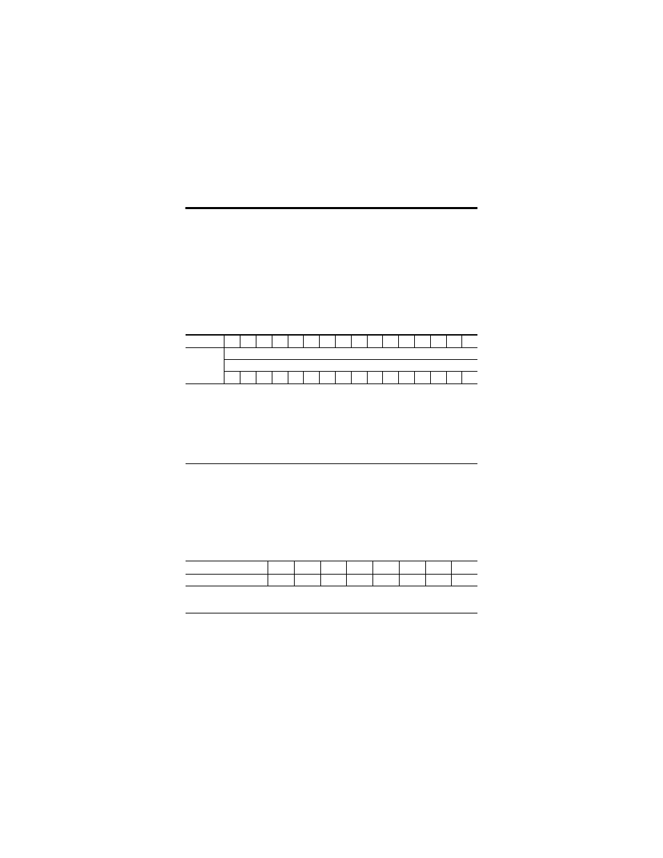
Default Data Map for 1734-IJ, 1734-IK
Message size: 6 or 10 Bytes
15
14
13
12
11
10 09
08
07
06
05
04
03
02 01
00
Produces
(scanner Rx)
Channel 0 value of present counter state (LSW)
Channel 0 value of present counter state (MSW)
PE
EF
NR
0
0
0
0
0
0
ZS
BS
AS
C1
C0
ZD
0
Where:
LSW = Least significant word
MSW = Most significant word
PE = Programming error
EF = EEPROM fault status
NR = Not ready status bit
ZS = Z input status
BS = B input status
AS = A input status
C1/C0 = Stored data count
ZD = Zero frequency detected
Message size: 1 Byte
07
06
05
04
03
02
01
00
Consumes (scanner Tx)
0
0
0
0
0
VR
CP
CR
Where:
VR = Value reset of stored/accumulated count
CP = Counter preset
CR = Counter reset