14 analog encoder (ae) servo module – Rockwell Automation 1756-M02AE Analog Encoder (AE) Servo Module Installation Instructions User Manual
Page 14
14 Analog Encoder (AE) Servo Module
Publication 1756-IN047D-EN-P - March 2001
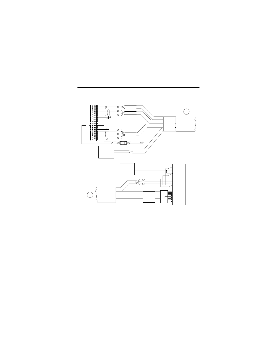
Figure 9 Wiring to a 1394 Servo Drive (in Torque Mode only)
Note:
The wiring diagram illustrates Axis 1 wiring only. Other
configurations are possible.
Note:
The 1394CCAExx cable is wired to connect to torque command
reference input pins.
Note:
An external +5V power supply is required to power the encoder
driver circuit of the 1394 servo drive. Because this connection is shared by all
four axis encoder driver circuits, only one connection is needed to the +5V
field supply.
Note:
The xx in the cable number is the length of the cable. Options are
5, 10, 25, and 50 feet.
5V DC
Field Power
Supply
+5V DC
+5 COM
RED
BLK
To fault
string
OK
RED
BLK
WHT
BLK
RED
BLK
WHT
BLK
RED
BLK
GRN
BLK
+OUT 0
-OUT 0
+ENABLE 0
-ENABLE 0
DRVFLT 0
CHASSIS
IN_COM
HOME 0
REG24V 0
REG5V 0
+OK
CHASSIS
+CHA 0
-CHA 0
+CHB 0
-CHB 0
+CHZ 0
-CHZ 0
+OUT 1
-OUT 1
+ENABLE 1
-ENABLE 1
DRVFLT 1
CHASSIS
IN_COM
HOME 1
REG24V 1
REG5V 1
-OK
CHASSIS
+CHA 1
-CHA 1
+CHB 1
-CHB 1
+CHZ 1
-CHZ 1
Servo Module RTB
1394CCAExx
24V DC
Field Power
Supply
1394 Servo Drive
1394CCAExx
WHT
BLK
RED
BLK
+ENABLE 1
-ENABLE 1
DRVFLT 1
IN_COM
TB2 7
TB2 19
TB2 18
W2
W1
TB2 15
24V DC
24V COM
24V DC
24V COM
24V ENABLE COM
A1 ENABLE
DROK
DROK
AQB1
A
RED OK+
BLK OK-
1756-M02AE
Axis 1
ENA/DR OK 1
ENC. PWR -1
A