G file, Output image table, G file output image table – Rockwell Automation 1746-QV,D17466.18 OPEN-LOOP VELOCITY CONTL User Manual
Page 32
SLC Processor Files
C–2
Publication 1746-6.18 April 1998
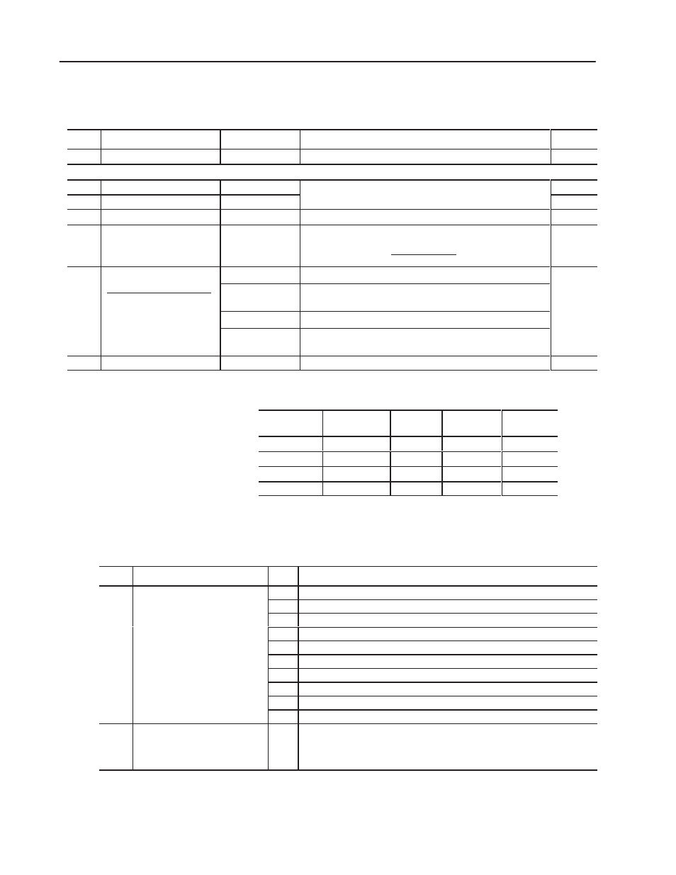
Use this file (Ge:0) to configure the module for use with the LDT.
Example values are those from the sample ladder logic (appendix B).
Word:
Function of G-file Word:
Range:
Description of G-file Word or Bit:
Example:
0
Reserved. Do NOT use.
n/a
The processor stores a code for the 1746-QV module.
2056
words 1 & 2 refer to the gradient or transducer calibration value stamped on the name plate on the transducer housing.
1
LDT calibration: upper 3 digits
800-999
ms/inch
For example: To enter an LDT calibration of 8.9373,
u e deci al radi and enter 893 in word 1 and 73 in word 2.
893
2
LDT calibration: lower 3 digits
000-999
ms/inch
For e a ple o enter an
calibration of 8.9373
use decimal radix and enter 893 in word 1 and 730 in word 2.
730
3
Full-scale length (L) of LDT
2
vLv160 inch
Enter the length of the LDT (160 inches max).
12
4
Full-scale count (C)
2
vCvLx100
Typically C = L x 100.
Position Data (I:e.1) = C/(L x 100)
LDT Calibration
1200
5
Configuration Bits
1 14 13 12- Equi alent Value
bits 0-12
Set to zero.
–32,768
bit 1 = 1
15 14 13 12-0 Equivalent Value
0 1 0 0
+16,384
1 0 0 0
–32,768
1 1
–16 384
bit 13
0 = output maintained during LDT fault or SLC mode change
1 = output resets for LDT fault or SLC mode change
(bit 15 = 1
for position
increases
toward
1 0 0 0
–32,768
1 1 0 0
–16,384
0 1 1 0
+24,576
bit 14
Type of LDT: 0 for RPM, 1 for DPM
increa e
towards
LDT head)
0 1 1 0
+24,576
bit 15
0 = position data increases when moving away from LDT head
1 = position increases when moving toward LDT head
head
6
Preset Reference
–32,768 to +32,767 Typically zero or home reference value. 32,767 = 327.67 inches.
0
Examples of Full-scale Count Values
LDT Physical
Length
No. of
Recirculations
Resolution
Full-scale
Length (L)
Full-scale
Counts (C)
from 160” to 2”
1
0.01
L (160” to 2”)
L x 100
16”
2
0.01
160
8000
16”
4
0.01
160
4000
16”
10
0.001
160
16000
The ladder program loads commands and profile data into the
module through the output image table, O:e.0–O:e.7.
Word:
Function of Output Image Word:
Bit #:
Description: (For command bits, a 0-to-1 transition enables the command)
0
Command Bits
0
Set to run an extend profile.
Co
and Bit
Enable the e bit
1
Set to run a retract profile.
Enable these bits
with our ladder logic.
2
Set to disable the profile. This bit over-rides bit 0 or 1.
with your ladder logic.
3
Set to change current position data to the value of preset reference in Ge:6.
4
Set to clear any data-entry errors.
5
Set to define words 1-7 as programmed position setpoints for extend.
6
Set to define words 1-7 as programmed voltage values for extend.
7
Set to define words 1-7 as programmed position setpoints for retract.
8
Set to define words 1-7 as programmed voltage values for retract.
9-15
Reserved. Do NOT use.
1-7
Position 1-7 Setpoint or Voltage
(i.e. word 2 = position 2, etc.)
n/a
Important:
Enter position setpoints in units of 0.01” (200 = 2.00”) within the range of
–327.68 to +327.67”, and voltage values in 5mV units (3005 = 3.005V)
within the range of
"10,000mV.
G File
Output Image Table